2 — INSTALLATION SPECIFICATIONS AND WIRING
pg. 25
Return to TOC Curtis Model 1351 – December 2018
Sine/Cosine Position sensors
e sine/cosine sensor has two analog signals 90 degrees out of phase. e output voltages are in the
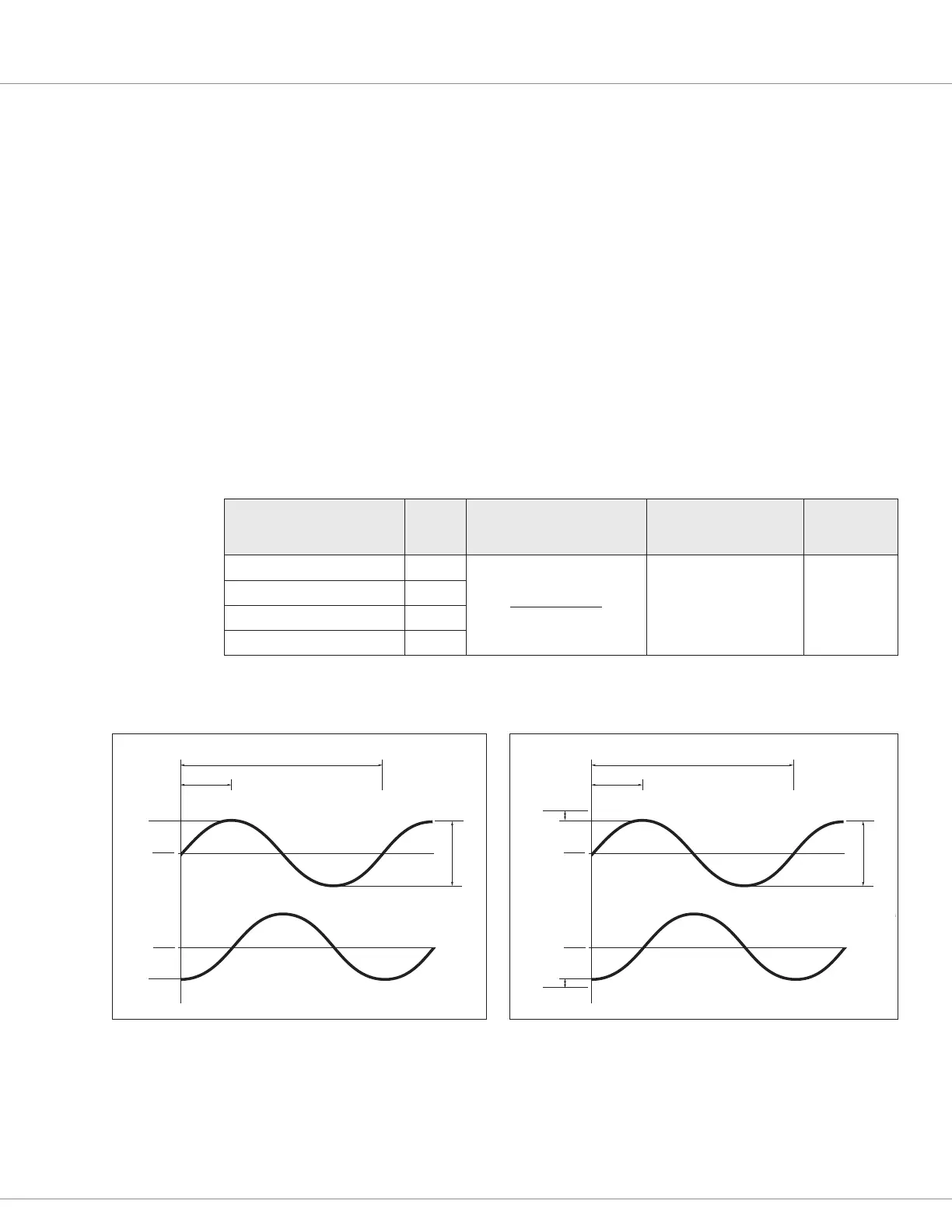
form of a sine and cosine over its sha 360-degree revolution. As illustrated below, the sensor must
be connected with one waveform cycle per mechanical revolution. e waveform tolerances must
be maintained throughout the application’s operating conditions, including voltage and temperature,
along with speed and torque ranges when applied to a motor. e waveform peaks must be away from
a 5V Vdd and ground by at least 0.5 V (i.e., the right-hand image). If the sensor voltages go outside
this range, position sensing will be faulty and not useable by the VCL functions. In this case, a fault
will be detected. Channels for sine (e.g., A) and cosine (B) are parameter selectable for direction—A
before B or B before A.
While a sin/cos sensor is typically used in Surface Permanent Magnet (SPM) motor applications, an
example 1351 application is linear-travel position, such as fork reach, where one revelation covers
the range from retracted to fully extended. Measurement and comparison of the two signals at any
point can determine the absolute position of the sensor and thus the forks location. e rate of signal
change versus time will equate to velocity.
Table 14 Sine/Cosine Sensor
Signal Name Pin Operating Voltage Max. Frequency
Input
Impedance
ENC 1A (Analog 4) / Sine 15
0 – 5 Vdd (typ.)
0.5 – 4.5 Vpp
200 Hz sinewave > 115 kΩ
ENC 1B (Analog 3) / Cosine 14
ENC 2A (Analog 2) / Cosine 2
ENC 2B (Analog 1) / Sine 1
360° mechanical (1 cycle)
V
pp
V
A
V
B
V
dd
Gnd
V
dd
2
V
dd
2
90°
360° mechanical (1 cycle)
V
pp
V
A
V
B
0.5 V
V
dd
Gnd
V
dd
2
V
dd
2
90°
0.5 V