2 — INSTALLATION SPECIFICATIONS AND WIRING
Curtis Model 1351 – December 2018
Return to TOC
pg. 26
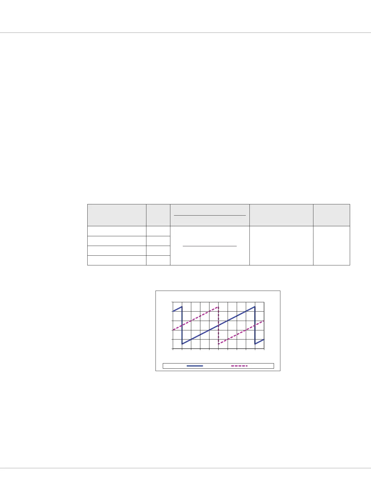
Sawtooth Position Transducer
e sawtooth transducer has two analog signals that ramp up as its sha rotates through 360 degrees.
As illustrated below, the signals are oset by 180 degrees. Unlike the sine/cosine sensor, each signal
provides an absolute indication of position, thus requiring a dierent set of setup parameters. e
signal voltage range must be set and the voltage that represents 0 degrees is required. If the analog
signals go outside the specied ranges for >60mS, a fault is declares. Also, if the position calculated
using the channel A is outside a tolerance parameter compared to channel B for >60mS, a fault will
be declared. e tolerances must be maintained throughout the application’s operating conditions,
including voltage and temperature, along with speed and torque ranges when applied to a motor.
As illustrated in the sawtooth waveform diagram, connect the sensor with one waveform cycle per
mechanical revolution. Channels for A and B are parameter selectable for direction—A before B or
B before A.
An example application is tracking linear-travel and position such as fork-reach where one revelation
covers the range from retracted to full extend. Another is for steering angle where one steering-wheel
rotation equates to one cycle (360°) of the sawtooth waveform(s).
Table 15 Sawtooth transducer
Signal Name Pin
Operating Voltage
Signal Range (peak to peak)
Max. Frequency
Input
Impedance
ENC 1A (Analog 4) / B 15
0 – 10 (min – max)
0 – 10.0 V
200 Hz > 115 kΩ
ENC 1B (Analog 3) / A 14
ENC 2A (Analog 2) / B 2
ENC 2B (Analog 1) / A 1
A B
0
1
2
3
4
5
-225-180-135 -90 -45 0 45 90 135 180 225
Volts [ V ]
Position [°]
Sawtooth Waveform