7 — DIAGNOSTIC AND TROUBLESHOOTING
Curtis Model 1351 – December 2018
Return to TOC
pg. 114
7 — DIAGNOSTIC AND TROUBLESHOOTING
e controller has two status LEDs, one red and one yellow LED. e present status of the controller
can be ascertainable within seconds by observing the status LEDs. Each fault will ash a specic code.
THE DIAGNOSTICS PROCESS
Diagnostics information can be obtained in either of three ways: (1) by observing the fault codes
ashed by the controller’s status indicator, (2) by reading the indicated fault (
) in the Curtis Soware
Suite
TM
Programmer app, or (3) the CAN Emergency Messages.
Table 22 species the condition and associated ash pattern for the 1351 System Controller LEDs.
Table 22 LED ash patterns
Condition Red Yellow Pattern
OK Off
Flashing at a 1.5 sec
cycle.
ON = 500 ms
Off = 1000 ms
Programming ON ON
Dead ON OFF
Error
Flash Code digit 1
250 ms ON
250 ms OFF
Flash Code digit 2
250 ms ON
250 ms OFF
Each code is followed by a
2-second pulse, and the next
code is started.
Invalid Software Fast Flash OFF
The Normal/OK state is shown by only on the yellow LED flashing a 1 at a 1.5 sec cycle rate.
Additionally, the On-time is lengthen to a full 500 ms, thus further dierentiates it from any Error
ash code.
Programming is shown using two formats:
• Initiate Programming and End of Programming = Both LEDs ON 100%,
• While data is incoming = Red LED ON and Yellow LED fast ashing
Non-operation (dead) state is shown by the RED Led 100% on and the Yellow LED o.
Error Codes (faults) are shown on the Status LEDs using a sequence of ashes and pauses. e
technique used is a departure from the previous Curtis motor controller standard (e.g., E/SE
controllers). e 1351 uses a format where the Red LED ashes the upper Tens digit number and
the Yellow LED ashes the lower Ones digit number. e ash cycle is 500 ms with a 250 ms On time.
If there are multiple codes, they are ashed in succession with a 2-second pause between each. ere
is an additional 2 seconds added to the last ash code in the list (4-second total pause) to denote the
last Error code has be ashed.
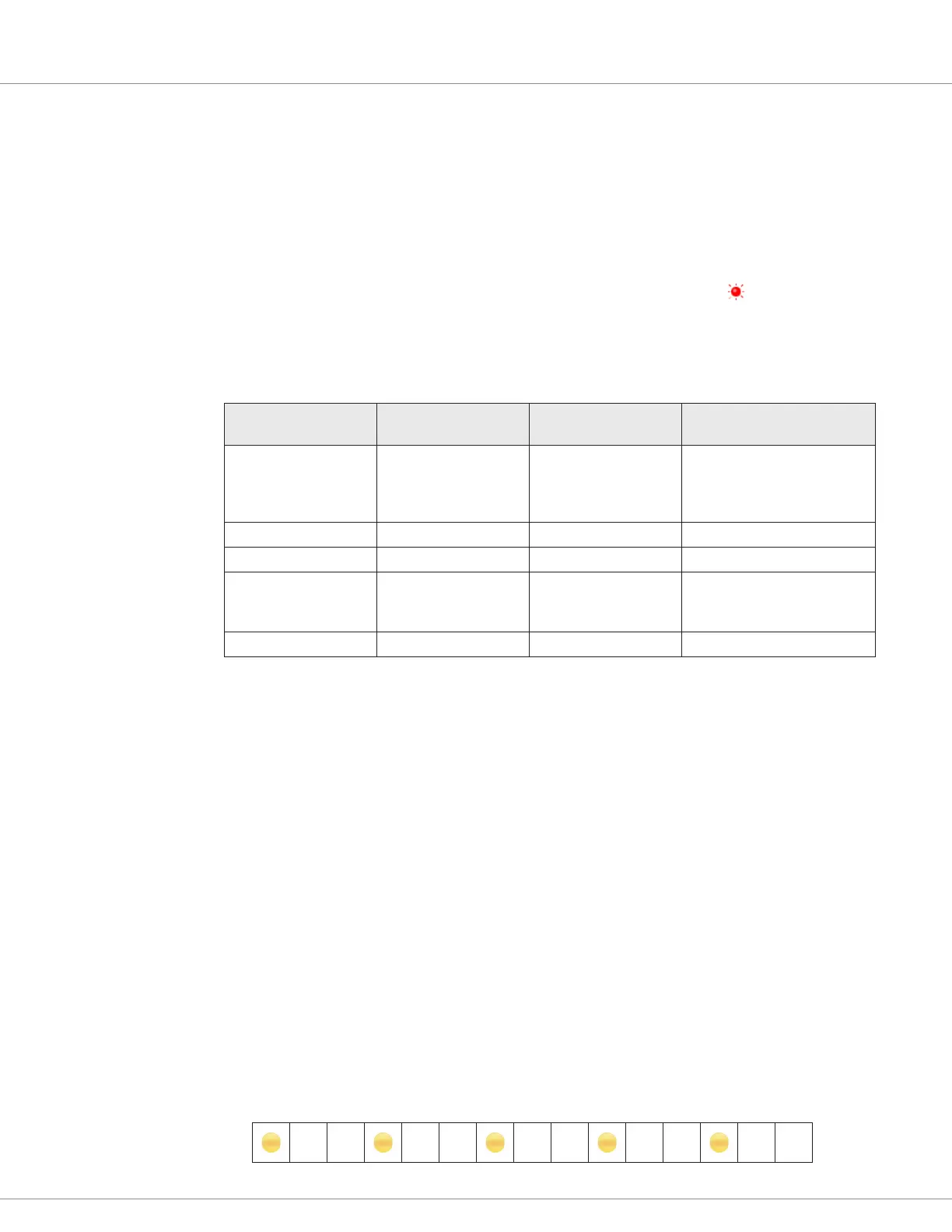
Examples: (Each block = 500 ms)
Normal/Ok/No errors
• On/O cycle within each block = 100% (thus, the On time is 500 ms)