EasyManuals Logo

Curtis Instruments 1351 User Manual

Default Icon
144 pages
To Next Page IconTo Next Page
To Previous Page IconTo Previous Page
Page #19 background imageLoading...
Page #19 background image
2 — INSTALLATION SPECIFICATIONS AND WIRING
pg. 13
Return to TOC Curtis Model 1351 – December 2018
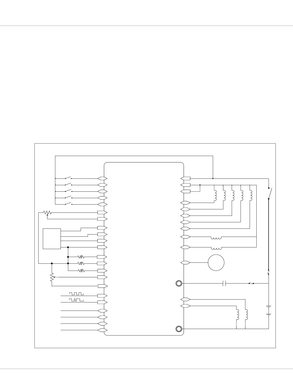
THE SYSTEM CONTROLLER’S WIRING DIAGRAM (EXAMPLE)
e 1351’s Inputs and Outputs (I/O) can easily conform to a wide range of applications. Use this chapter
and Chapter 3’s parameters information for insight into using and setting up each type of I/O. Figure
4 is the example-wiring diagram using the 1351 as an ICE driven hydraulic systems controller. In this
example, the Li/Lower and Steer Angle potentiometers connections are 3-wire potentiometer inputs,
while the control of the main contactor is by another device. Figure 4’s connections are representative
of just some of the possible 1351 System Controller wiring congurations.
Note: In cases where an applications wiring and I/O usage deviates from the wiring shown in Figure 4,
it is up to the OEM to evaluate the overall system safety. Always ensure a conguration is thoroughly
tested and veried for the application.
Figure 4
Example Wiring Diagram
1351 System Controller




Encoder


+12V
+5V




















KSI












11
12
Gauge







{
{








Engine Temp



33
4
3
6
5
10
2
1
8
29
30
31
32

21
20
22
9



14
25
34
28
27
26
24
13

35
23
17
16
Oil Temp
Oil Pressure
15
19
18
(B+ for the PWM drivers)
}

Table of Contents

Questions and Answers:

Question and Answer IconNeed help?

Do you have a question about the Curtis Instruments 1351 and is the answer not in the manual?

Curtis Instruments 1351 Specifications

General IconGeneral
BrandCurtis Instruments
Model1351
CategoryI/O Systems
LanguageEnglish