2 — INSTALLATION SPECIFICATIONS AND WIRING
Curtis Model 1351 – December 2018
Return to TOC
pg. 16
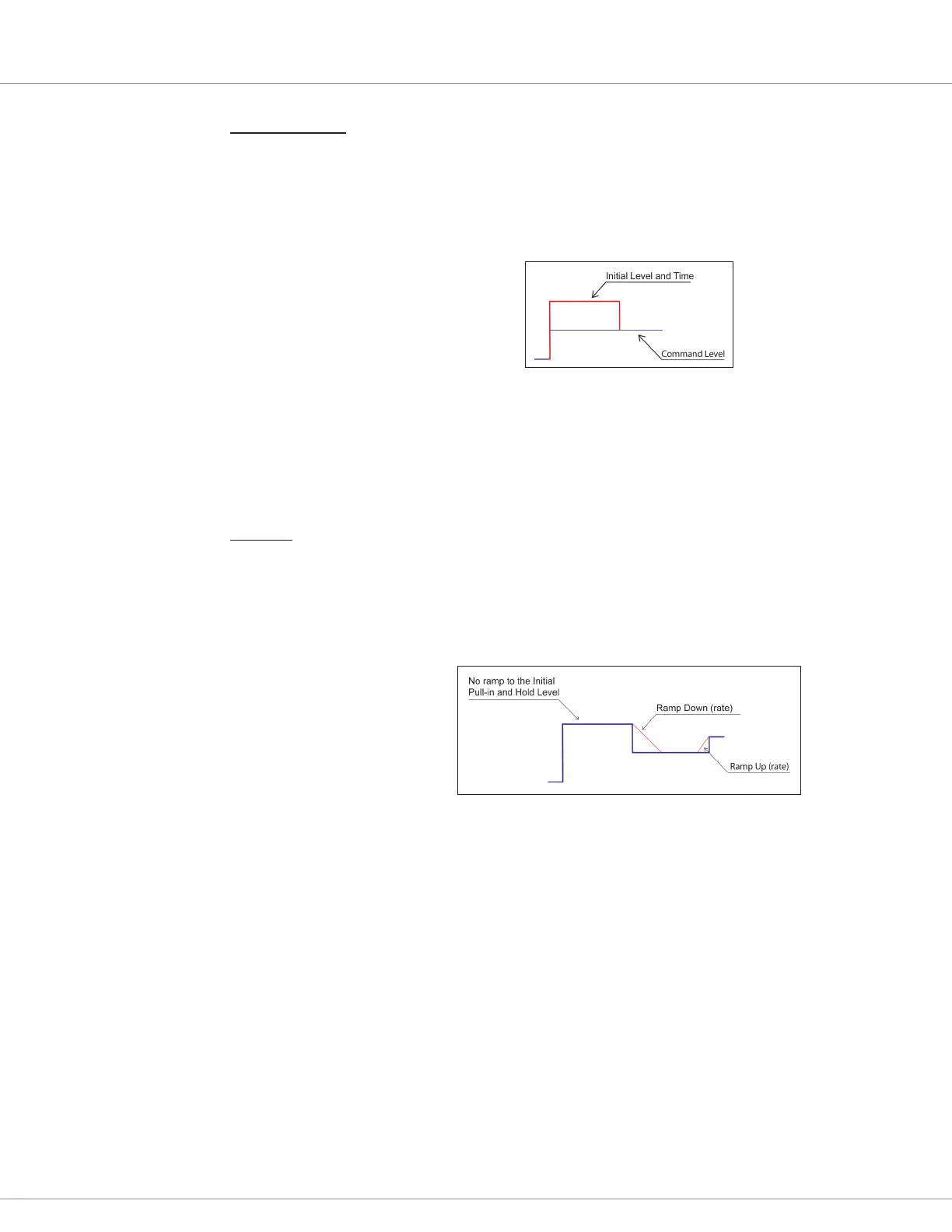
Pull-in and Hold e Pull-in and Hold function works on the raw VCL command (Driver_X_
Command) and is applied before the Ramping Function (see below). This
function provides a time at an Initial Level and then the rest of the time at the
applied command. e function is reset each time the command goes to 0%.
e Initial Level may be above or below the applied command. e gure below
represents an Initial level that was above the applied command.
Pull-in and Hold function
Typically, the Initial Command is above the applied (hold) command as it
provides a strong initial pull-in of the contactor tips, aer which the lower
hold-value reduces coil losses and heat when the contactor is closed. It can
also be set low to allow a jump function to some “minimum” value that is
commend without any ramp.
Ramping Each driver’s ramping functions occur following the commanded pull-in and
hold. Following the initial ramp functions, the ramping applies to all changes in
the nal driver command. ere are separate parameter values for ramping up
and ramping down the command. Note that the initial pull-in command value is
jumped-to and not ramped. (Setting the initial time and initial value of 0 defeats
the pull-in function and the ramp up be applied to the rst command from 0%).
Ramp-Down and Up function
e ramping times are the time it takes to go between the drivers' set minimum
command to the driver’s maximum command. In direct PWM, this is from 0
to 100% PWM, but in the Current controlled mode, this is from the Minimum
to the Maximum Current parameters. If these parameters are changed, the
actual ramp time will stay consistent as programmed, but the nal “rate” will
change.
e drivers can be commanded by directly writing to the variable Driver_X_Command, where the
value of 0 – 1000 commands from 0.0 – 100.0% PWM. e other applicable VCL driver functions are
Automate_Driver() and Put_Driver() as listed in Table 2.
e output drivers can also be used as digital inputs (switches 1–10) and are included in that group as
well. e wiring example, Figure 4, illustrates drivers 6-10 as switched inputs.