3 — PROGRAMMABLE PARAMETERS
pg. 39
Return to TOC Curtis Model 1351 – December 2018
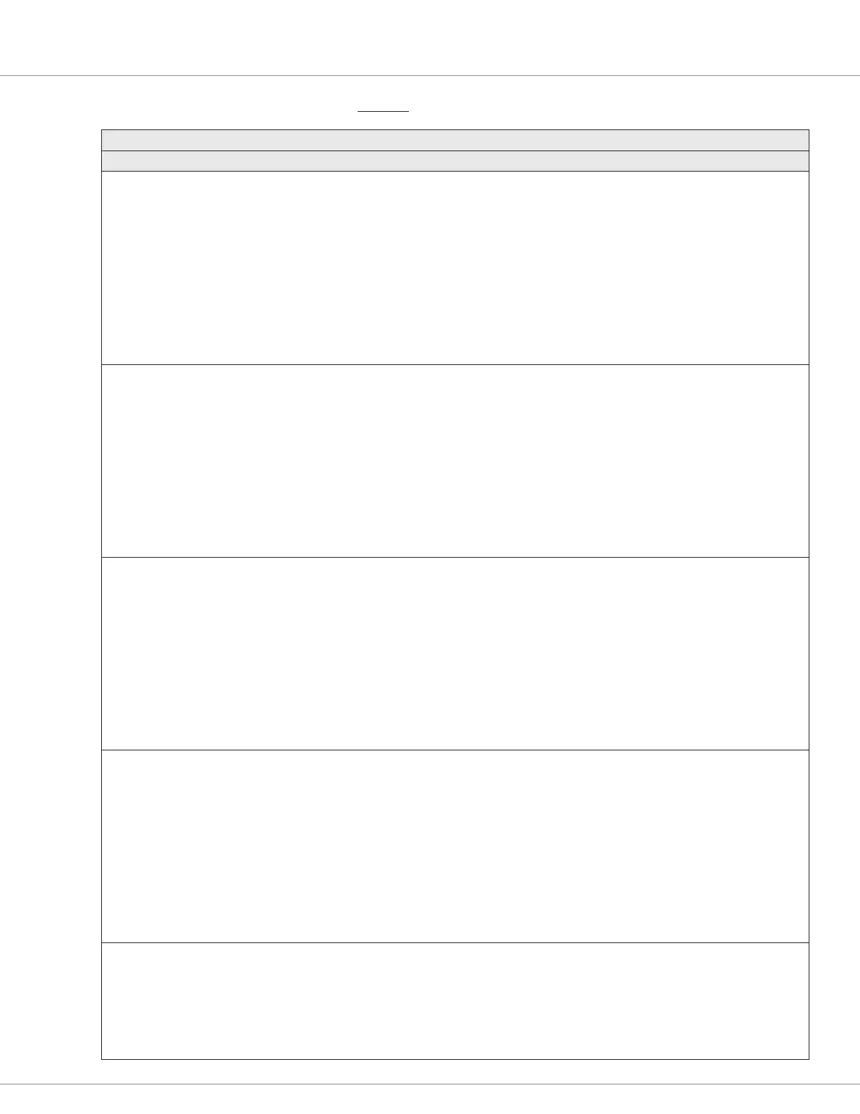
PARAMETER ALLOWABLE RANGE DEFAULT DESCRIPTION
SW2 through SW8: X = the Switch Number, which is part of the VCL parameters’ name (see SW1 as the example)
Status
Switch_X
Variable’s CAN Index by Switch
No.
2 = 0x338C 0x00
3 = 0x338D 0x00
4 = 0x338E 0x00
5 = 0x338F 0x00
6 = 0x3390 0x00
7 = 0x3391 0x00
8 = 0x3392 0x00
Off – On
0 – 1
Read Only Switch X Status: ON or OFF
This is the same variable as in the monitor menu:
Monitor » Inputs » Switch Input » Switch X
Note: This pin can be used as the PWM Driver (see Figure 4)
Open State
Switch_X_Open_State
Parameter’s CAN Index by
Switch No.
2 = 0x31F1 0x00
3 = 0x31F2 0x00
4 = 0x31F3 0x00
5 = 0x31F4 0x00
6 = 0x31F5 0x00
7 = 0x31F7 0x00
8 = 0x31F8 0x00
Pull Down – Pull Up
0 = Pull-down
1 = Pull-up
Pull Down
0
Select either the Pull-down or the Pull-up input option.
See the description for SW1, above.
Active Level
Switch_X_Active_Level
Parameter’s CAN Index by
Switch No.
2 = 0x3201 0x00
3 = 0x3202 0x00
4 = 0x3203 0x00
5 = 0x3204 0x00
6 = 0x3205 0x00
7 = 0x3207 0x00
8 = 0x3208 0x00
Low – High
0 = Low
1 = High
High
1
Select the active ON state of the input.
See the description for SW1, above.
Debounce
Switch_X_Debounce
Parameter’s CAN Index by
Switch No.
2 = 0x3211 0x00
3 = 0x3212 0x00
4 = 0x3213 0x00
5 = 0x3214 0x00
6 = 0x3215 0x00
7 = 0x3217 0x00
8 = 0x3218 0x00
0 – 1000 ms
0 – 1000
0
0
Length of time that the switch state must be steady (active)
before it is declared (valid).
See the description for SW1, above.
The voltage at the pin does not indicate if the switches 1 – 8 are open or closed (OFF or ON). The OFF or ON state depends upon how the switch is
connected and congured. A “closed” switch can be connected to I/O Ground (B-) or it can be connected to KSI (B+).
• If the application is to consider B− or B+ to be the ON state, this is set using the Active State parameter.
• If the application is to consider an open input to be high or low, this is set using the Open State parameter.
Note that if the Open State is set to Pull-up, the external pin must switch to I/O Ground (B−) else the switch position (ON or OFF) cannot be sensed.
Likewise, if the Open State is set to Pull-down, the external pin must switch to KSI (B+), else the switch position (ON or OFF) cannot be sensed.
INPUTS — SWITCHES, cont’d