EasyManua.ls Logo

Curtis Instruments 1351 User Manual

Default Icon
144 pages
To Next Page IconTo Next Page
To Previous Page IconTo Previous Page
Page #98 background imageLoading...
Page #98 background image
5 — VEHICLE CONTROL LANGUAGE (VCL)
Curtis Model 1351 – December 2018
Return to TOC
pg. 92
 Check_SDO_Read() Check if a specic request for SDO data has been fullled

Check_SDO_Read(Reception_ID)
:
Reception_ID Specify the buer handle provided by the Request_
SDO_Read function
:
0 = waiting for the message to be received. (i.e., cannot send
another read request until the previous request has populated
the buer). Needs a check and/or delay in the VCL main loop
to prevent over-requesting.
1 = Message Received
2 – 11 = Abort code (see table)
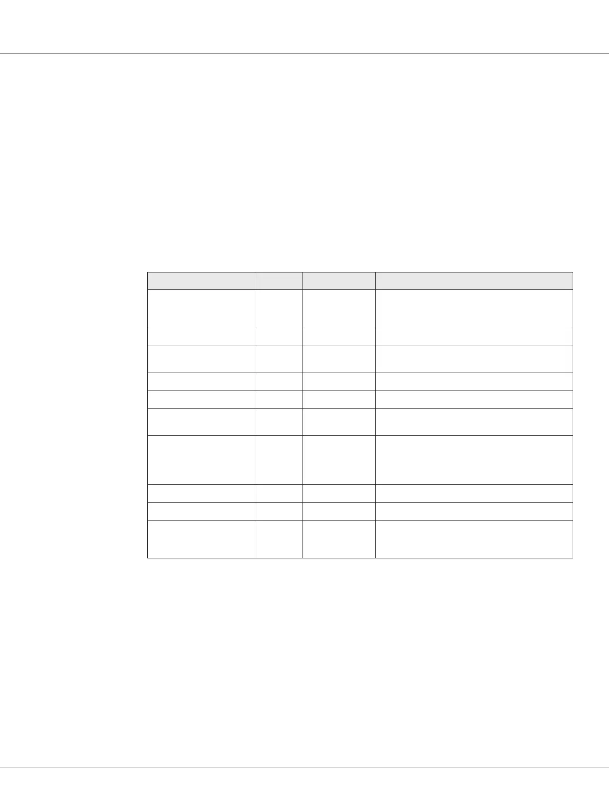
Error Message Return CANopen Code Description
BAD_SDO_COMMAND 2 0504 0001h
Anytime the SDO command byte is unknown or the
SDO structure is incorrect, including wrong length
(not 8 bytes, as required by the CCIS-V2 device)
CRC_FAILED 3 0504 0004h The CRC failed on the le.
UNSUPPORTED_ACCESS 4 0601 0000h
Attempt to access an object using an incorrect
access level.
OBJECT_IS_WRITE_ONLY 5 0601 0001h Try to read a write-only object
OBJECT_IS_READ_ONLY 6 0601 0002h Try to write a read-only object
UNSUPPORTED_OBJECT 7 0602 0000h
Object is not in the device, or an error occurred
while in a block, or segmented SDO transfer.
PDO_MAPPING_ERROR 8 0604 0041h
Any PDO mapping failure, including a non-
map-able parameter, the device is not in Pre-
Operational mode, the length byte is wrong or
there are too many bytes in the PDO mapping.
VALUE_OUT_OF_RANGE 9 0609 0030h The value is out-of-range
GENERAL_ERROR 10 0800 0000h Any other generic reason not listed elsewhere.
INVALID_DEVICE_STATE 11 0800 0022h
Some parameters cannot be changed if the system
is moving or is engaged (interlock off) or if the fault
has not occurred
 :
 Variable = Get_SDO_Length() Return the number of valid bytes in the
SDO reception

Get_SDO_Length(Reception_ID)
:
Reception_ID Specify the buer handle provided by the request
function
:
Number of valid bytes that were returned by the SDO
request
 :

Table of Contents

Questions and Answers:

Curtis Instruments 1351 Specifications

General IconGeneral
CategoryI/O Systems
Model1351
Operating Temperature Range-40°C to +85°C
Protection FeaturesOvervoltage, Short Circuit
Communication InterfaceCAN 2.0B

Summary

1 — OVERVIEW

How to Use This Manual

Explains how to use the manual's content and structure.

Getting the Most Out of Your Curtis Controller

Tips for optimal use and contact for technical support.

2 — INSTALLATION SPECIFICATIONS AND WIRING

Mounting and Safety Precautions

Guidelines for physical mounting and general safety warnings.

Wiring and Connections

Details on AMPSEAL connector, battery, low-power wiring, and voltages.

Input/Output Configuration

Overview of various input and output types and their configurations.

Communication Ports and Power

Details on CAN ports, power supply outputs, and keyswitch connections.

3 — PROGRAMMABLE PARAMETERS

Programming Menus and Format

Overview of parameter menus, chart format, and terminology.

System Controller Parameters

Parameters for power, BDI, external supplies, and temperature.

Input Parameters

Configuration for switches, virtual switches, analog, pot, RTD, high-speed, encoder inputs.

Output Parameters

Configuration for PWM drivers, half-bridge, digital drivers, safety, and analog outputs.

CAN Parameters

Settings for CAN ports and communication protocols.

4 — MONITOR VARIABLES

System Controller Monitor Variables

Read-only variables for system controller status and measurements.

Input Monitor Variables

Read-only variables for various input types like switches, analog, and encoders.

Output Monitor Variables

Read-only variables for PWM drivers, half-bridge drivers, and digital outputs.

Accelerometer Monitor Variables

Read-only variables for the 3-axis accelerometer data.

5 — VEHICLE CONTROL LANGUAGE (VCL)

VCL Overview and Basics

Introduction to VCL, its capabilities, and fundamental programming rules.

Variables and Constants

Explanation of VCL variable types, memory storage, and constants.

VCL, Watchdog Timer and Faults

Setting up watchdog timers and defining fault actions within VCL code.

CAN Functions (VCL Setup)

VCL functions for CAN setup, message handling, and NMT control.

SDO Management

VCL functions for managing Service Data Objects (SDOs) read/write operations.

CAN Mailbox Operations

Functions for allocating and configuring CAN mailboxes for data transmission/reception.

SRDO Functions

VCL functions for Safety Related Data Objects transmission and reception.

6 — INITIAL SETUP & COMMISSIONING

Initial Setup and Preparation

Steps for initial setup, safety, and preparation before commissioning.

Parameter Settings Method Overview

Recommended sequence for setting hardware and software parameters.

Output Parameter Configuration

Procedure for configuring PWM, half-bridge, digital, and analog outputs.

Fault Clearing Procedure

Steps to check, clear, and resolve controller faults and history.

7 — DIAGNOSTIC AND TROUBLESHOOTING

The Diagnostics Process

Methods for obtaining diagnostics information via LEDs, software, or CAN messages.

Error Flash Code Interpretation

Explanation of LED flash patterns and their meanings for fault codes.

8 — MAINTENANCE

Cleaning Procedures

Recommended procedure for cleaning the controller exterior.

Fault History Management

Accessing, checking, and clearing the controller's fault history file.

APPENDIX A — VCL FUNCTIONS

General VCL Functions

Core VCL functions for various operations like interpolation, timing, and scaling.

CANopen Functions

VCL functions for CANopen mailbox setup and configuration.

SRDO Functions

VCL functions for Safety Related Data Objects transmission and reception.

APPENDIX B — VEHICLE SYSTEM DESIGN CONSIDERATIONS-&-RECYCLING

Electromagnetic Compatibility (EMC)

Guidelines for EMC performance, emissions, RF immunity, and noise reduction.

Decommissioning and Recycling the Controller

Procedures for controller removal from OEM vehicle and disposal.

APPENDIX C — PROGRAMMING DEVICES FOR THE 1351

Curtis Software Suite™

PC-based software for controller setup, parameter adjustment, and diagnostics.

Curtis 1313 Handheld Programmer

Standalone programmer and diagnostic tool for the system controller.

APPENDIX D — EN 13849 COMPLIANCE

Safety-Related Performance Analysis

Summary of safety performance levels (PL, MTTFd, DC) for controller circuits.

APPENDIX E — 1351 MODELS AND SPECIFICATIONS

Table E Model Chart and Specifications

Technical specifications, model comparison, and environmental ratings.