CVC TECHNOLOGIES, INC. CVC 310 OPERATION MANUAL
7 - 3
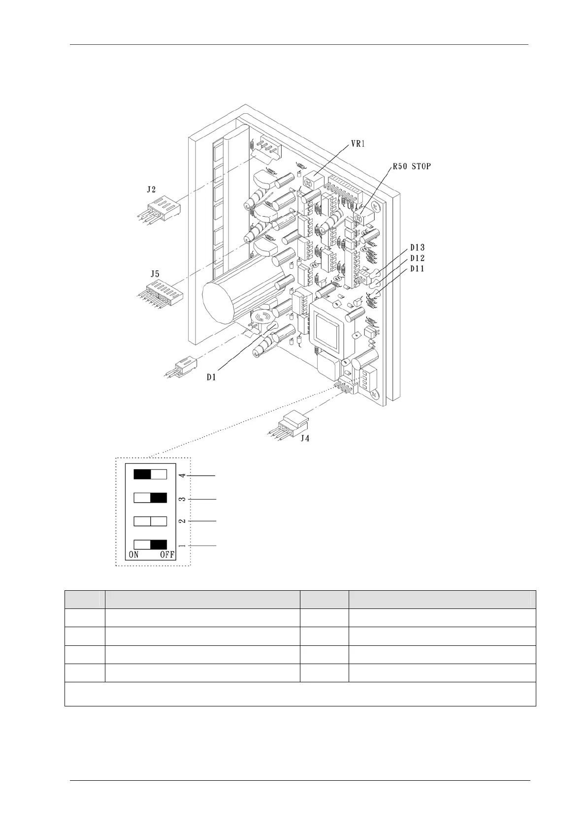
Stepper Motor Driver - Label Head
Item Description Item Description
JP2 Driver power DC 145V D1 DC 145 Power indicator
J2 Stepper motor output D11 Labeling signal indicator
J4 Power control for 5V/12V D12 Spare – for future use
J5 Signal input & energy saving mode D13 Power indicator
Fuse for stepper motor driver is located at side board. LED 37 is lit when F2 fuse is burned. Replace a new fuse and a new
stepper motor driver.
Fig
7.2-1
Dip Switch setting:
Left: Overheating protection
Spare – for future use.
Left: Single Label Head stepper motor revolution switch
Right: Half step motor switch: 0.9˚ revolution per signal.
JP2:Driver
ower DC 145V