15
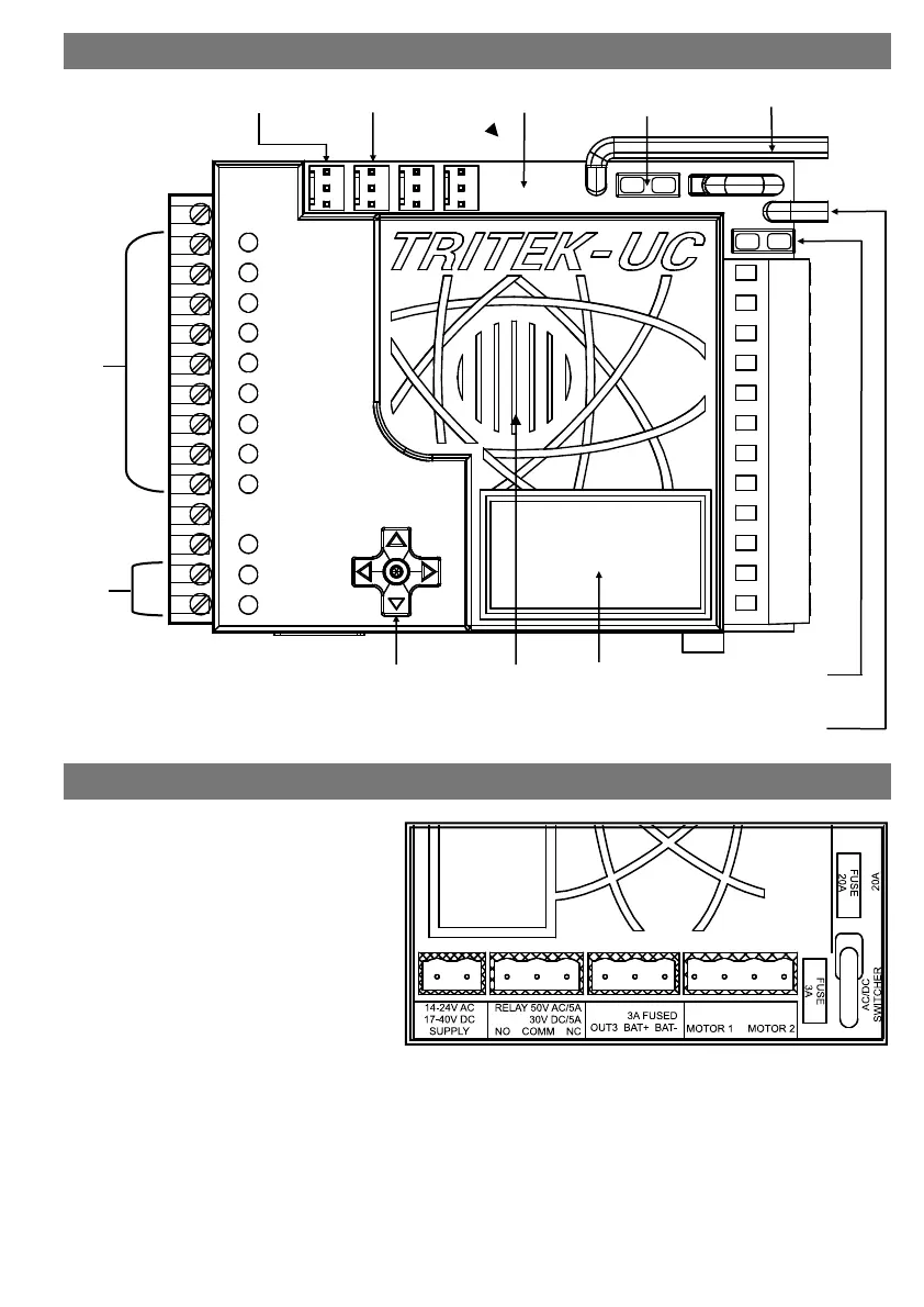
FUSE 20A: this fuse protects the motor in
the event of a short circuit or excessive
overload.
FUSE 3A: this fuse protects the auxiliary
baery output in the event of a short cir-
cuit or excessive overload.
MOTOR 1: this output is used to drive the
motor.
BAT-: this is the baery negave pole.
BAT+: this is a fused 3A auxiliary baery
output that is used for powering Electric &
Mag locks.
OUT3: this output must be connected to a Relay Module (SA001) for switching Pillar lights & Strobe warning
lights. Explore the LCD menus to adjust the many dierent opons available.
RELAY: this output is used for switching Electric or Mag locks.
SUPPLY: Connect 14V AC to 24V AC or unregulated solar power (max. of 40V DC). Minimum supply current
1.5A.
INPUT CONNECTIONS
OUTPUT
CONNECTIONS
MARKER
INPUT
GSM/WiFi
INPUT
20A FUSE
MOTOR
BATTERY –VE
JOYSTICK LCD SPEAKER
REV COUNTER
INPUT
BATTERY +VE
12V - 24V
3A FUSE
BATTERY AUX OUTPUT
TRITEK CONTROL BOARD LAYOUT
OVERVIEW OF POWER CONNECTIONS & FUSES