8
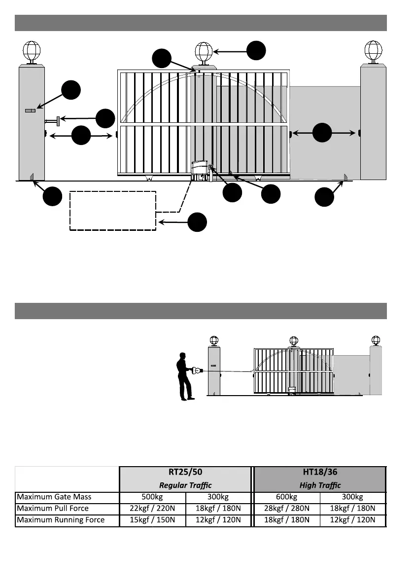
SITE LAYOUT
GATE PULL & RUNNING FORCES
1. Intercom Gooseneck
2. Catch Bracket
3. Close Safety Beam
4. End Stop
5. Exit Loop
6. Isolator Switch
7. Marker Magnet
8. Open Safety Beam
9. Guide Rollers
10.Pillar Light
1
9
8
5
6
7
2
3
4
10
The gate Pull and Running Forces must be
measured before installing the operator. Should
the measured forces exceed those in the table
below, then the operator must not be installed.
It may be possible to reduce these forces by
carrying out maintenance on the gate & rail but
if not, then the operator must not be installed.
These forces can be measured using a shing or
luggage scale (see gure alongside)
Pull Force: place the gate in the fully open/closed posion and pull on the scale unl the gate starts moving. The
value showing on the scale at the point that the gate starts moving is the Pull Force kgf.
Running Force: this is the maximum value read while the gate is moving before coming to the fully open posion.
4