33
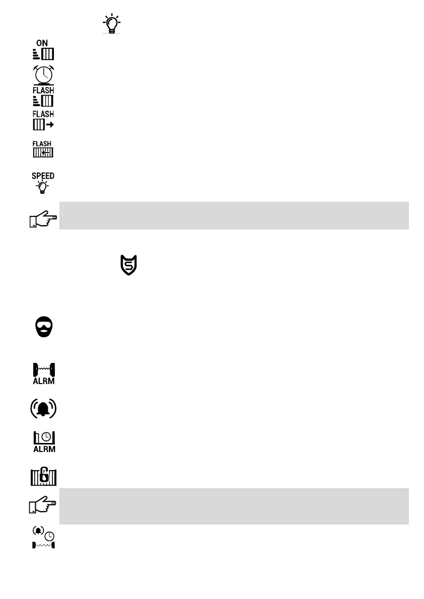
LIGHT SETTINGS
Courtesy Light
Usually used to switch pillar lights on when the operator is triggered. The light output must be connected
to an EXO Relay Module. Do not connect mains directly to the controller.
Set Light Timer
This function sets the length of time that the light will remain on if the Courtesy Light option is enabled.
Flash On Moving
If enabled, the light connected to the light output on the controller will ash while the gate is moving.
Pre Close Flash
If enabled, the light will start ashing before the gate closes if the ‘Pre Close Delay’ opon is set, either
via the ‘Pedestrian Entry’ menu or the ‘ Gate Setup -> Run Prole’ menu.
Pre Open Flash
If enabled, the light will start ashing when the gate is acvated if the ‘Pre Open Delay’ opon is set,
either via the ‘Pedestrian Entry’ menu or the ‘Gate Setup -> Run Prole’ menu.
Flashing Speed
This seng adjusts the ashing speed of the light from 0.25 - 6 seconds. Dierent types of lights have
dierent response mes. Incandescent lights might, for instance, need to be ashed slower than LED
lights.
Fluorescent energy saver bulbs should not be used for warning signals. These lights have special circuitry
which may be damaged by ashing the light and might also damage the controller. It is recommended
that either LED, halogen or incandescent lights are used.
SECURITY SETTINGS
The following Alarm Funcons, if enabled, will acvate the controller’s Alarm output. This output, connected via
an EXO Relay Module, can acvate a buzzer; siren or house alarm. If a GSM Module is ed, all alarm signals will
be transmied to selected cell phone numbers.
Ambush Alarm
If enabled, this funcon will acvate the controller’s alarm output if any of the Safety Beams are blocked
for a period longer than the me set in ‘Ambush IR Timer’, when the gate is in the open/ing posion. This
can occur if an intruder blocks the safety beams, when a homeowner enters the property, to prevent the
gate from closing.
Break In Alarm
When enabled, this funcon will acvate the controller’s alarm output immediately if any of the Safety
Beams are blocked while the gate is in the closed posion. This eecvely makes the Safety Beams
perform a funcon like that of Perimeter Beams.
Tamper Alarm
If enabled, this funcon will acvate the controller’s alarm output if the gate operator’s lid is lied up.
This feature is only available on operators where the oponal tamper switch has been installed.
Gate Open Alarm
If enabled, this funcon acvates the controller’s alarm output if the gate remains open for a period
longer than the me set in ‘Stand Open Time’. This warns the homeowner if the gate is le open or is
unable to close (could be as a result of a fault or an obstrucon).
Securi-Lock
If enabled, this funcon will acvate the controller’s alarm output if the gate is forced open while in the
closed posion.
Important: To enable this feature, rst place the gate in the closed posion and move the Marker
Magnet (see pg. 14) from the prescribed posion on the gate to right in front of the Marker Sensor (see
pg.7, part number 14). When the feature is enabled the controller will automacally re-detect the
Marker Magnet’s posion by moving the gate o the marker and returning back to it.
Ambush IR Timer
This mer sets the maximum duraon that the beams may remain blocked while the gate is in the open
posion (See Ambush Alarm) before acvang the controller’s alarm output (1 sec- 5 min).
Connues……...