5-163 MISCELLANEOUS CONTROLS AND OPTIONS
10. HYDRAULIC DEVICE OF CAR CARRIER
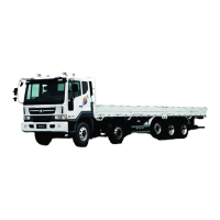
Circuit diagram
8
7
6
4
9
1.
2.
3.
Oil tank
Suction strainer
Gear pump
1
1
1
5
4.
5.
6.
7.
8.
9.
Solenoid relief valve
Return valve
Stopping valve
Pressure gauge
Oil hose - Socket
Oil hose - Plug
MTF1000
Operation
Hydraulic pressure is generated by gear pump driven by PTO. Oil with high pressure is then trans-
ferred to the unit of the car carrier and its pressure is maintained below(4) solenoid relief valve preset
pressure (100kg/cm
2
). Operation of solenoid valve is activated by a switch on car-carrier unit with a
PTO switch while the key is 'ON'.
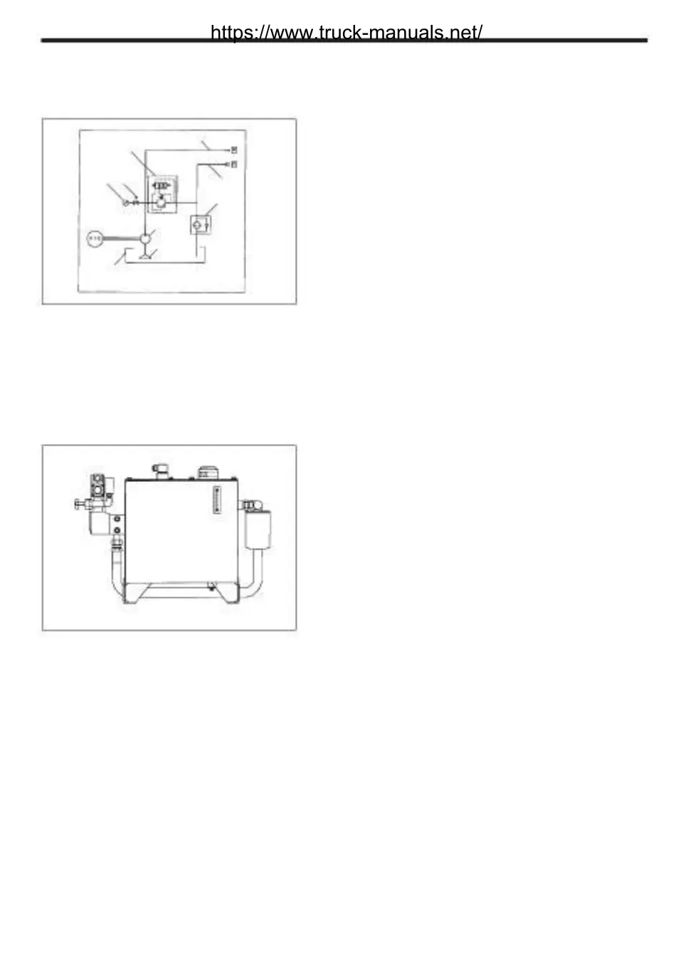
Oil tank
1. Oil capacity : 301 (up to the indication mark of
gauge)
2. Suction strainer : Passing by flow : 501/min(mesh
150)
3. Oil type : ISO VG 32
4. Interval for replacement : Every 1 year after initial
change at 3 months.
(Suction strainer needs to be replaced at the same
time)
MTF1010
https://www.truck-manuals.net/