Pilot's Operating Handbook
Section 7
Description
Edition 1 - January 15, 2018
Rev. 4
Page 7.3.2
>> Before digital hourmeter installation (Pre-MOD70-0533-31A)
An hourmeter is located above circuit breakers panel.
>> All
An adjustable air outlet is located on both sides of instrument panel lower part.
Reception-micro jacks are located inside the recess under the arm-rest on both lateral
sides of the cockpit, on R.H. side of intermediate R.H. passenger's seat and on the
arm-rest of rear R.H. passenger's seat.
Pedestal console - see figure 7.3.6
The pedestal console, under the touchscreen controllers, comprises flaps controls,
pitch trim tab control wheel, aileron trim switch, engine controls and fuel tank selector.
Circuit breakers panel - see figures 7.3.7 and 7.8.4
Circuit breakers for all electrical equipment supplied by bus bars are located on a
separate panel installed on the right side of cockpit.
General alarms warning lights and CAS messages
WARNING , CAUTION and ADVISORY messages appear on the MFD CAS
window to alert crew about monitored systems discrepancies. As a message
appears, a chime is heard. Refer to the GARMIN Pilot's Guide to know all possible
CAS messages.
A MASTER WARNING red flashing indicator and a MASTER CAUTION amber
indicator located on instrument panel - see figure 7.3.8, in front of the pilot, illuminate
as soon as one or several messages of same color light on.
To cancel and reset a general alarm, press on the red or amber indicator. A pressure
on the red indicator also stops red message associated chimes.
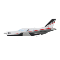
Aural warnings - see figure 7.3.2
The aural warnings are intended to alert the pilot during some configurations. The
aural signals are heard through the loud-speakers installed in cockpit overhead panel
and through the pilot's and R.H. station headsets.
The aural warnings consist of :
- the GARMIN flight deck system (GIA and GMA),
- the loud-speaker.
The system uses :
- the stall warning system,