Actual Signals
Several actual signals are available:
• Drive output frequency, current, voltage and power
• Motor speed and torque
• Circuit DC voltage
• Active control location (LOCAL, EXT1 or EXT2)
• Drive temperature
• Operating time counter (h), kWh counter
• Digital I/O and analog I/O status
Three signals can be shown simultaneously on the assistant
control panel display (one signal on the basic panel display).
It is also possible to read the values through the serial
communication link or through the analog outputs.
Table 12: Actual Signals Settings
Table 13: Actual Signals Diagnostics
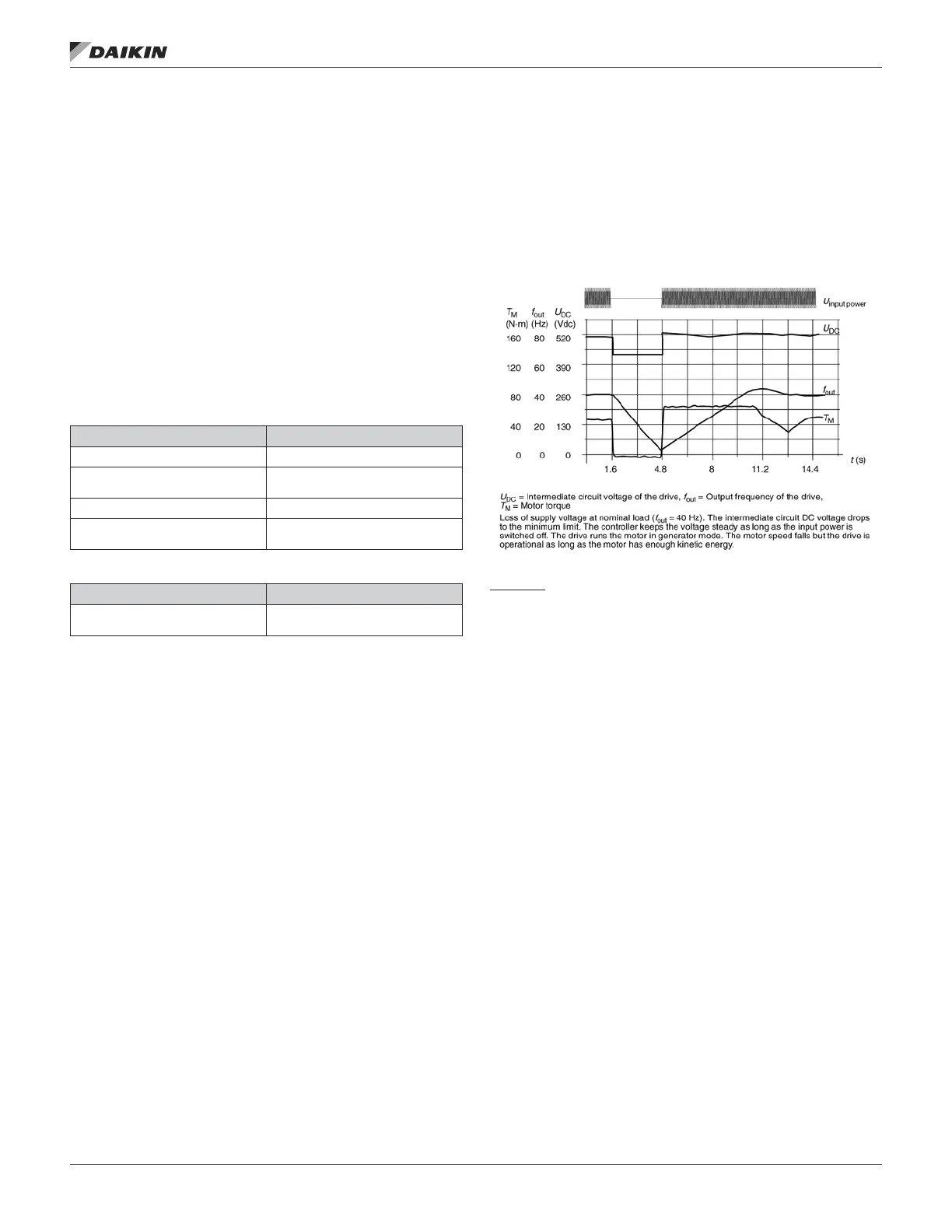
Power Loss Ride-Through
If the incoming supply voltage is cut off, the drive will continue
to operate by utilizing the kinetic energy of the rotating motor.
The drive will be fully operational as long as the motor rotates
and generates energy to the drive. The drive can continue
the operation after the break if the main contactor remained
closed.
Figure 18: Power Loss Ride-Through Diagram
Settings
Parameter 2006 UNDERVOLT CTRL, page 48
Parameter Additional Information
1501 Selection of an actual signal to AO
1801
Selection of an actual signal to
frequency output
Group 32: Supervision Actual signal supervision
Group 34: Panel Display Process
Variables
Selection of an actual signals to be
displayed on the control panel
Actual Signal Additional Information
Group 01: Operating Data … Group
04: Fault History
Lists of actual signals
OM 1190-1 • MD4 VFD 26 www.DaikinApplied.com
program feaTures