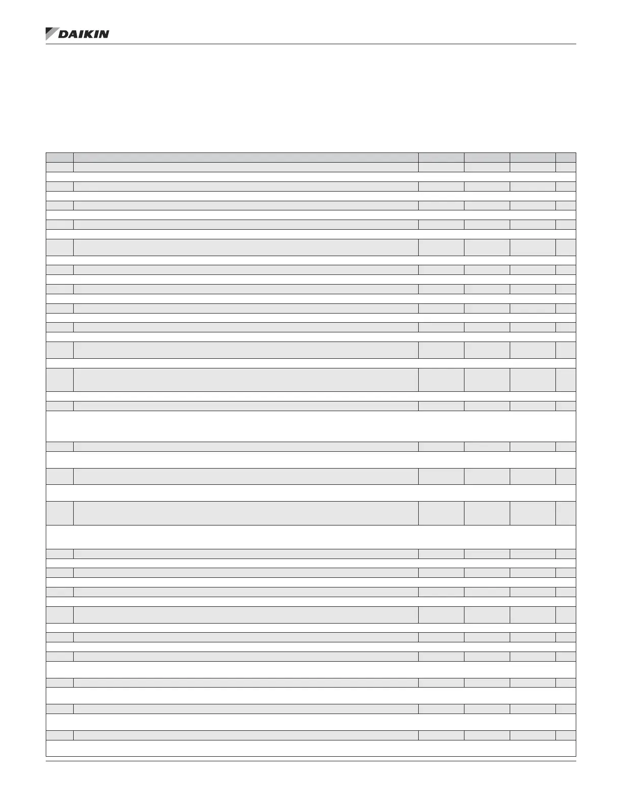
Group 01: Operating Data
This group contains drive operating data, including actual
signals. The drive sets the values for actual signals, based on
measurements or calculations. You cannot set these values.
Table 23: Group 01: Operating Data
Code Description Range Resolution Default S
0101 SPEED & DIR -30000...30000 1 rpm —
The calculated speed of the motor (rpm) & motor direction.
0102 SPEED 0...30000 rpm 1 rpm —
The calculated speed of the motor (rpm).
0103 OUTPUT FREQ 0.0...500.0 Hz 1Hz —
The frequency (Hz) applied to the motor. (Also shown by default in OUTPUT display.)
0104 CURRENT 0.0...1.5*I2N 0.1 A —
The motor current, as measured by the ACH550. (Also shown by default in OUTPUT display.)
0105 TORQUE
-200%…
200%
0.1% —
Output torque. Calculated value of torque on motor shaft in % of motor nominal torque.
0106 POWER -1.5…1.5*PN 0.1 kW —
The measured motor power in kW.
0107 DC BUS VOLTAGE 0 V…2.5*VdN 1 V —
The DC bus voltage in VDC, as measured by the ACH550.
0109 OUTPUT VOLTAGE 0 V…2.0*VdN 1 V —
The voltage applied to the motor.
0110 DRIVE TEMP 0°C…150°C 1°C —
The temperature of the drive power transistors in Centigrade.
0111 EXTERNAL REF 1
0...30000 rpm
/ 0...500 Hz
1 rpm / 0.1 Hz —
External reference, REF1, rpm or Hz - units determined by parameter 9904.
0112 EXTERNAL REF 2
0%...100%
(torque:
0%...600%
0.1% —
External reference, REF2, in %
0113 CTRL LOCATION 0...2 1 —
Active control location. Alternatives are:
0 = HAND
1 = EXT1
2 = EXT2
0114 RUN TIME(R) 0...65,535 h 1 h 0 h
The drive’s accumulated running time in hours (h).
• Can be reset by pressing UP and DOWN buttons simultaneously when in parameter set mode.
0115 KWH COUNTER (R)
0...65,535
kWh
1 kWh —
The drive’s accumulated power consumption in kilowatt hours.
• Can be reset by pressing UP and DOWN buttons simultaneously when in parameter set mode.
0116 APPL BLK OUTPUT
0...100%
(torque:
0...600%)
0.1% —
Application block output signal. Value is from either:
• PFA control, if PFA Control is active, or
• Parameter 0112 EXTERNAL REF 2.
0120 AI1 0...100% 0.1% —
Relative value of analog input 1 in %.
0121 AI2 0...100% 0.1% —
Relative value of analog input 2 in %.
0124 AO1 0...20 mA 0.1 mA —
The analog output 1 value in milliamperes.
0126 PID 1 OUTPUT
-1000...1000%
0.1% —
The PID Controller 1 output value in %.
0127 PID 2 OUTPUT -100...100% 0.1% —
The PID Controller 2 output value in %.
0128 PID 1 SETPNT — — —
The PID 1 controller setpoint signal.
• Units and scale dened by PID parameters 4006/4106 & 4007/4107.
0129 PID 2 SETPNT — — —
The PID 2 controller setpoint signal.
• Units and scale dened by PID parameters 4206 & 4207.
0130 PID 1 FBK — — —
The PID 1 controller feedback signal.
• Units and scale dened by PID parameters 4006/4106 & 4007/4107.
0131 PID 2 FBK — — —
The PID 2 controller feedback signal.
• Units and scale dened by PID parameters 4206 & 4207.
aCTual sIgnals and parameTers
www.DaikinApplied.com 33 OM 1190-1 • MD4 VFD