Connecting the Control Cables
This section applies only to units shipping without MicroTech
controllers but need eld controls installed.
I/O Terminals
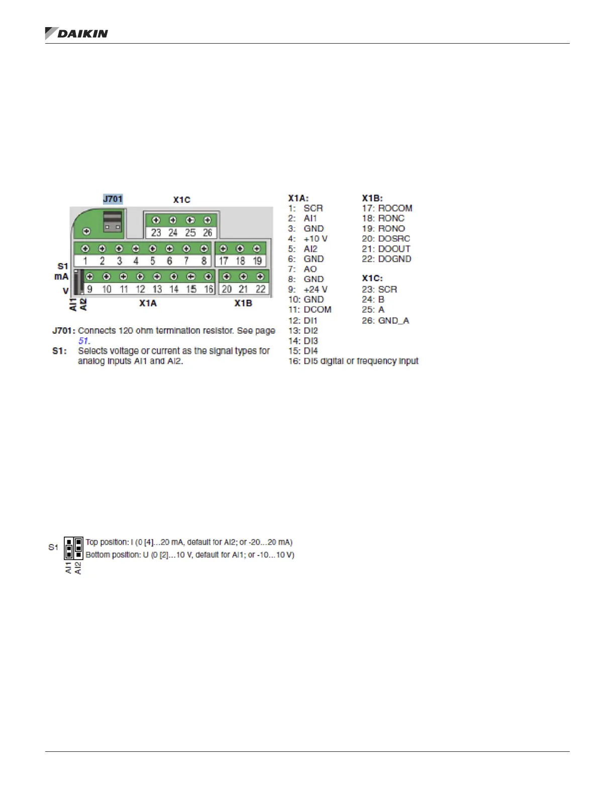
Figure 4 shows the I/O terminals. Tighten torque is 0.4 Nm/3.5
in-lbs.
Figure 4: I/O Terminals
Voltage and Current Selection for
Analog Inputs
Switch S1 selects voltage (0 [2]…10 V / -10…10 V) or current
(0 [4]…20 mA / -20…20 mA) as the signal types for analog
inputs AI1 and AI2. The factory settings are unipolar voltage
for AI1 (0[2]…10V) and unipolar current for AI2 (0[4]…20mA),
which correspond to the default usage in the application
macros. The switch is located to the left of I/O terminal 9,
Figure 4.
Figure 5: Voltage and Current Switch Locations
Permenently afx control cables with a minimum 1/4" spacing
from power cables.
OM 1190-1 • MD4 VFD 10 www.DaikinApplied.com
operaTIon prInCIple/Hardware desCrIpTIon

 Loading...


