Group 26: Motor Control
This group provides controls for ne-tuning the motor control.
Table 36: Group 26: Motor Control
Code Description Range Resolution Default S
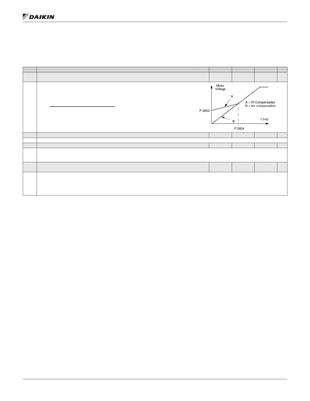
2603 IR COMP VOLT 0…100 V 1 V
Size
Dependent
Sets the IR compensation voltage used for 0 Hz.
• Requires parameter 9904 MOTOR CTRL MODE = 3 (SCALAR SPEED).
• Keep IR compensation as low as possible to prevent overheating.
• Typical IR compensation values are:
380…480 V Units
PN (kW) 3 7.5 15 37 132
IR comp (V) 18 15 12 8 3
IR Compensation
• When enabled, IR Compensation provides an extra voltage boost to the motor at low speeds.
Use IR Compensation, for example, in applications that require a high breakaway torque.
2604 IR COMP FREQ 0…100% 1 80%
Sets the frequency at which IR compensation is 0 V (in % of motor frequency).
2605 U/f RATIO 1, 2 1 2
Selects the form for the U/f (voltage to frequency) ratio below eld weakening point.
1 = LINEAR – Preferred for constant torque applications.
2 = SQUARED – Preferred for centrifugal pump and fan applications. (Square is more silent for most operating frequencies.)
2606 SWITCHING FREQ
1, 4, 8, 12,
16 kHz
— 4 kHz
Sets the switching frequency for the drive.
• Higher switching frequencies mean less noise.
• The 1, 4 and 8 kHz switching frequencies are available for all frame sizes R1-R6.
• The 12 kHz switching frequency is available only if parameter 9904 MOTOR CTRL MODE = 3 (SCALAR:FREQ).
NOTE: Selecting 12 kHz switching frequency automatically limits parameter 9906 to 0.80 of drive nameplate FLA.
OM 1190-1 • MD4 VFD 52 www.DaikinApplied.com
aCTual sIgnals and parameTers