Group 35: Motor Temp Meas
This group denes the detection and reporting for a particular
potential fault – motor overheating, as detected by a
temperature sensor. Typical connections are dened below.
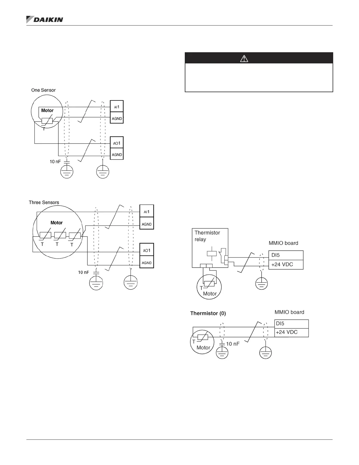
Figure 20: One Sensor Connection
Figure 21: Three Sensor Connection
WARNING
IEC 60664 requires double or reinforced insulation between
live parts and the surface of accessible parts of electrical
equipment which are either non-conductive or conductive but
not connected to the protective earth.
To fulll the insulation requirement, connect a thermistor (and
other similar components) to the drive’s control terminals using
any of these alternatives:
• Separate the thermistor from live parts of the motor with
double reinforced insulation.
• Protect all circuits connected to the drive’s digital and
analog inputs. Protect against contact, and insulate from
other low voltage circuits with basic insulation (rated for
the same voltage level as the drive’s main circuit).
• Use an external thermistor relay. The relay insulation
must be rated for the same voltage level as the drive’s
main circuit.
The gure below shows alternate thermistor connections.
At the motor end the cable shield should be earthed through
a 10 nF capacitor. If this is not possible, leave the shield
unconnected.
Figure 22: Alternate Thermistor Connections
For other faults, or for anticipating motor overheating using a
model, see Group 30: Fault Functions, page 53.
aCTual sIgnals and parameTers
www.DaikinApplied.com 59 OM 1190-1 • MD4 VFD