Product Overview
Layout
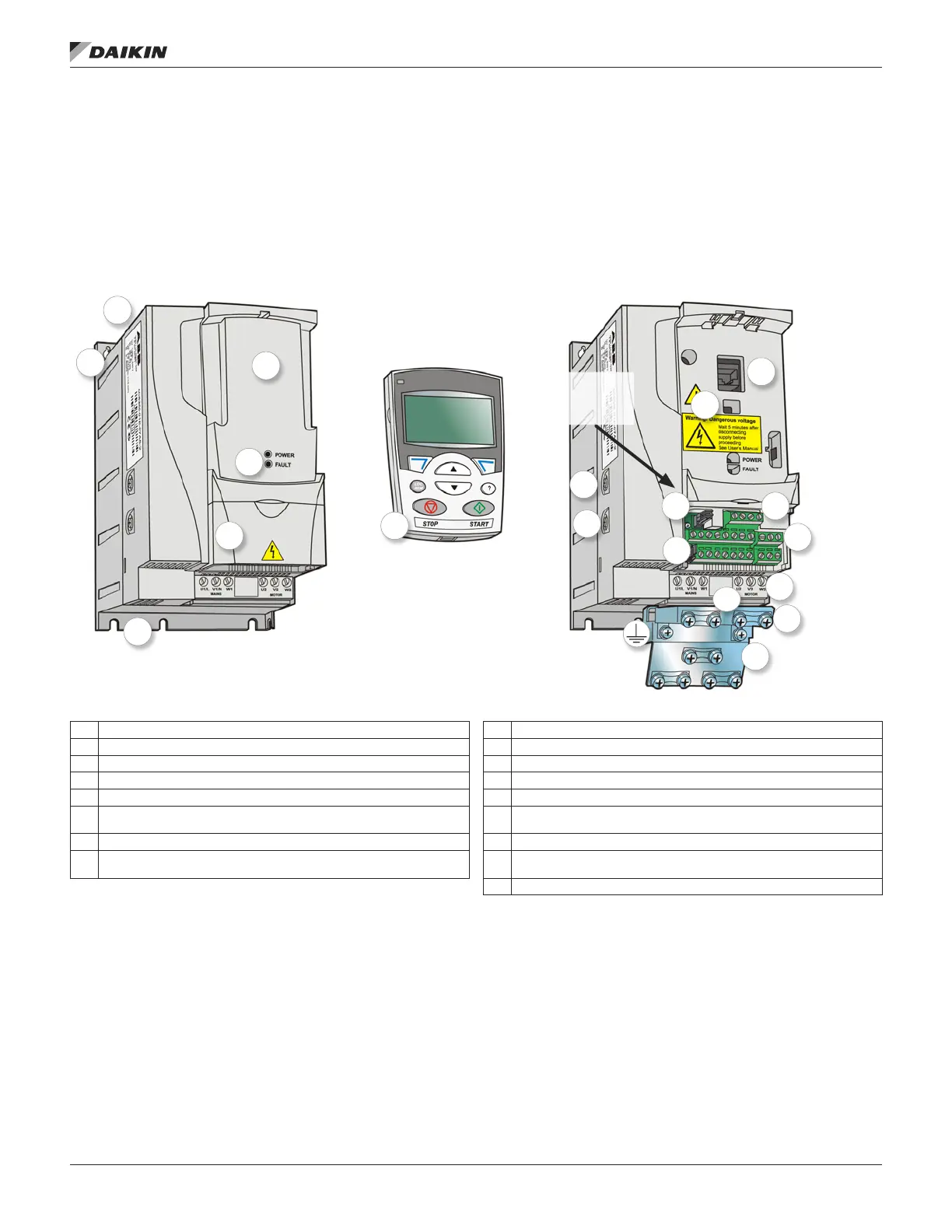
The layout of the drive is presented in Figure 2. The gure
shows a frame size R2 drive. The construction of the different
frame sizes R0…R4 varies to some extent.
Power Connections and Control
Interfaces
Figure 3 gives an overview of connections. I/O connections are
parameterable. See Application Macros on page 72 for I/O
connections for the different macros.
Figure 2: Drive Components
1 Cooling outlet through top cover 9 Varistor grounding screw (VAR)
2 Mounting holes 10 RS-485 connection
3 Panel cover (a) / Assistant Control Panel (c) 11 Jumper J701 for connecting RS-485 termination resistor
4 Terminal cover 12 I/O connections
5 Panel connection 13 Switch S1 for selecting voltage or current for analog inputs
6 Option connection 14
Input power connection (U1, V1, W1) and motor connection (U2, V2, W2).
(Braking chopper connection is disabled.)
7 Power OK and Fault LEDs. See section LEDs on page 101. 15 I/O clamping plate
8
EMC lter grounding screw (EMC). Note: The screw is on the front in frame
size R4.
16 Clamping plate
17 Clamps
1
9
2
2
10
3a
3b
11
4
12
5
13
6
14
7
15
8
16
17
J701 Switch
for RS-485
Termination
OM 1190-1 • MD4 VFD 8 www.DaikinApplied.com
operaTIon prInCIple/Hardware desCrIpTIon