Analog Output Control
Using the eldbus for analog output control requires:
• Drive parameter values set as dened below.
• Fieldbus controller supplied reference word(s) in the
appropriate location. (The location is dened by the
Protocol Reference, which is protocol dependent.)
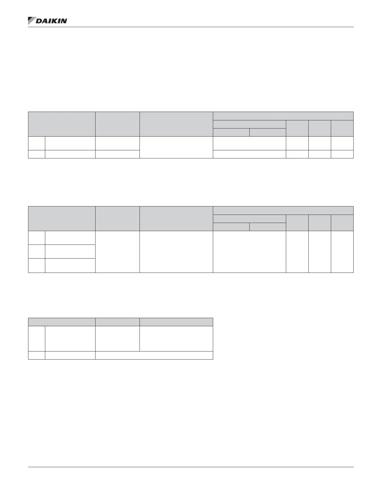
Table 55: Analog Output Control Protocol Reference
Drive Parameter Value Setting
Protocol Reference
Modbus
N2 FLN BACnet
abb drv dcu prole
1501 AO1 CONTENT SEL
135
(COMM VALUE 1)
Analog Output 1 controlled by
writing to parameter 0135.
— — — —
0135 COMM VALUE 1 — 40135 AO14 46 AO0
PID Control Setpoint Source
Use the following settings to select the eldbus as the setpoint source for PID loops:
Table 56: PID Control Setpoint Source Protocol Reference
Drive Parameter Value Setting
Protocol Reference
Modbus
N2 FLN BACnet
abb drv dcu prole
4010
SET POINT SEL
(Set 1)
8 (COMM VALUE 1)
9 (COMM + AI1)
10 (COMM*AI1)
Setpoint is either: Input Reference
2 (+/-/* AI1). Control requires
parameter 1106 value = comm.
Process PID setpoint. Control
requires parameter 1106 value =
pid1 out and parameter 4010 value
= comm.
40003 AO2 61 AV17
4110
SET POINT SEL
(Set 2)
4210
SET POINT SEL (Ext/
Trim)
Communication Fault
When using eldbus control, specify the drive’s action if serial communication is lost.
Table 57: Communication Fault Reference
Drive Parameter Value Description
3018 COMM FAULT FUNC
0 (NOT SEL)
1 (FAULT)
2 (CONST SP7)
3 (LAST SPEED)
Set for appropriate drive response.
3019 COMM FAULT TIME Set time delay before acting on a communication loss.
OM 1190-1 • MD4 VFD 78 www.DaikinApplied.com
fIeldbus ConTrols