Group 34: Panel Display Process Variables
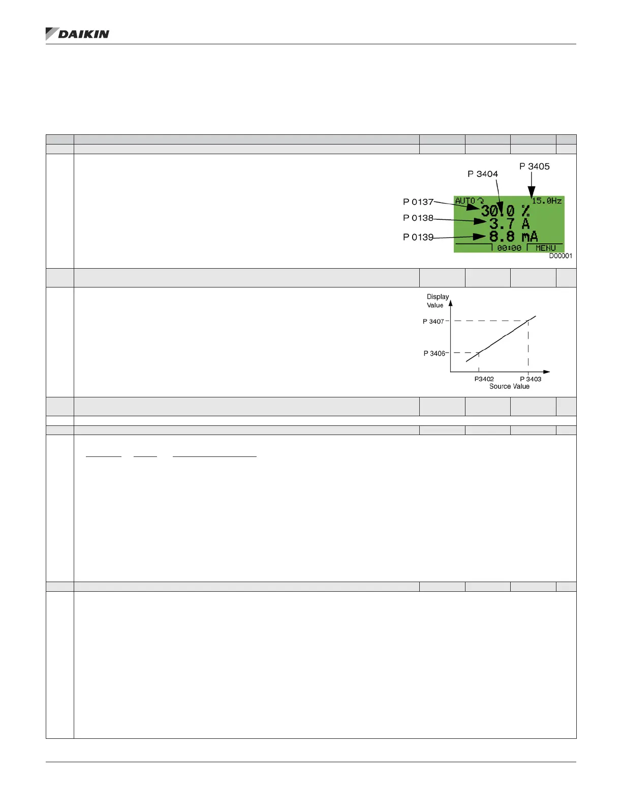
This group denes the content for control panel display (middle area), when the control panel is in the output mode.
Table 40: Group 34: Panel Display Process Variables
Code Description Range Resolution Default S
3401 SIGNAL1 PARAM 100…199 1 103
Selects the rst parameter (by number) displayed on the control panel.
• Denitions in this group dene display content when the control panel is in the control mode.
• Any Group 01 parameter number can be selected, page __.
• Using the following parameters, the display value can be scaled, converted to convenient units,
and/or displayed as a bar graph.
• The gure identies selections made by parameters in this group.
100 = not selected – First parameter not displayed.
101…199 = Displays parameter 0101…0199. If parameter does not exist, the display shows “n.a.”.
3402 SIGNAL1 MIN
Depends on
selection
0.0 Hz
Denes the minimum expected value for the rst display parameter. Use parameters 3402, 3403,
3406, and 3407, for example to convert a Group 01 parameter, such as 0102 SPEED (in rpm) to the
speed of a conveyor driven by the motor (in ft/min). For such a conversion, the source values in the
gure are the min. and max. motor speed, and the display values are the corresponding min. and
max. conveyor speed. Use parameter 3405, page 57 to select the proper units for the display.
Note: Selecting units does not convert values.
3403 SIGNAL1 MAX
Depends on
selection
— 600.0 Hz
Denes the maximum expected value for the rst display parameter.
3404 OUTPUT1 DSP FORM 0…9 1 9
Denes the decimal point location for the rst display parameter.
3404 Value Display Range
0 + 3 -32768…+32767 (Signed)
1 + 3.1
2 + 3.14
3 + 3.142
4 3 0…65535 (Unsigned)
5 3.1
6 3.14
7 3.142
1…7 – Denes the decimal point location.
• Enter the number of digits desired to the right of the decimal point.
• See table for example using pi (3.14159).
8 = BAR METER – Species a bar meter display.
9 = DIRECT – Decimal point location can vary depending on source signal but does not affect unit operation.
3405 OUTPUT1 DSP UNIT 0…127 1 4
Selects the units used with the rst display parameter.
0 = NOT SEL 12 = mV 24 = GPM 36 = l/s 48 = gal/m 60 = ft wg
1 = A 13 = kW 25 = PSI 37 = l/min 49 = gal/h 61 = lbsi
2 = V 14 = W 26 = CFM 38 = l/h 50 = ft3/s 62 = ms
3 = Hz 15 = kWh 27 = ft 39 = m3/s 51 = ft3/m 63 = Mrev
4 = % 16 = °F 28 = MGD 40 = m3/m 52 = ft3/h 64 = d
5 = s 17 = hp 29 = inHg 41 = kg/s 53 = lb/s 65 = inWC
6 = h 18 = MWh 30 = FPM 42 = kg/m 54 = lb/m 66 = m/min
7 = rpm 19 = m/s 31 = kb/s 43 = kg/h 55 = lb/h 67 = Nm
8 = kh 20 = m3/h 32 = kHz 44 = mbar 56 = FPS 68 = Km3/h
9 = °C 21 = dm3/s 33 = Ohm 45 = Pa 57 = ft/s
10 = lb ft 22 = bar 34 = ppm 46 = GPS 58 = inH2O
11 = mA 23 = kPa 35 = pps 47 = gal/s 59 = in wg
117 = %ref 119 = %dev 121 = % SP 123 = Iout 125 = Fout 127 = Vdc
118 = %act 120 = % LD 122 = %FBK 124 = Vout 126 = Tout
aCTual sIgnals and parameTers
www.DaikinApplied.com 57 OM 1190-1 • MD4 VFD