Group 40: Process PID Set 1
This group denes a set of parameters used with the Process
PID (PID1) controller.
Typically only parameters in this group are needed and are
only needed for units shipping without MicroTech controllers
but need eld controls installed..
PID Controller – Basic Set-up
In PID control mode, the drive compares a reference signal
(setpoint) to an actual signal (feedback), and automatically
adjusts the speed of the drive to match the two signals. The
difference between the two signals is the error value.
Typically PID control mode is used, when the speed of a fan
or pump needs to be controlled based on pressure, ow or
temperature. In most cases – when there is only 1 transducer
signal wired to the ACS320 – only parameter group 40 is
needed.
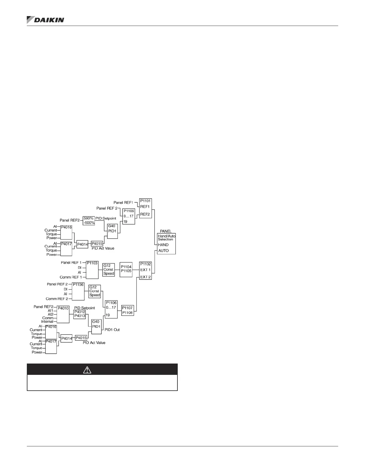
A Schematic of setpoint/feedback signal ow using parameter
Group 40 is presented.
Figure 23: Signal Flow Diagram
WARNING
In order to activate and use the PID controller Parameter
1106, page 39 must be set to value 19.
PID Controller – Advanced
ACS320 has 2 separate PID Controllers:
• Process PID (PID1) and
• External PID (PID2)
Process PID (PID1) has 2 separate sets of parameters:
• Process PID (PID1) SET1, dened in Group 40 and
• Process PID (PID1) SET2, dened in Group 41
You can select between the 2 different sets by using parameter
4027.
Typically two different PID-Controller sets are used when the
load of the motor changes considerably from one situation to
another.
You can use External PID (PID2), dened in Group 42, in 2
different ways:
• Instead of using additional PID-controller hardware,
you can set outputs of the ACS320 to control a eld
instrument like a damper or a valve. In this case, set
Parameter 4230 to value 0. (0 is the default value.)
• You can use External PID (PID2) as an additional PID-
controller to Process PID (PID1) to trim or ne-tune the
speed of the ACS320.
An example of the trimming is a return fan that follows the
speed of the supply fan. As the return fan needs to run faster
or slower then the supply fan in order to create under- or
overpressure, correction factors to the supply fan speed are
needed. Use External PID (PID2) in the return fan drive to
provide these corrections.
OM 1190-1 • MD4 VFD 62 www.DaikinApplied.com
aCTual sIgnals and parameTers

 Loading...


