Table 43: Group 40: Process PID Set 1
Code Description Range Resolution Default S
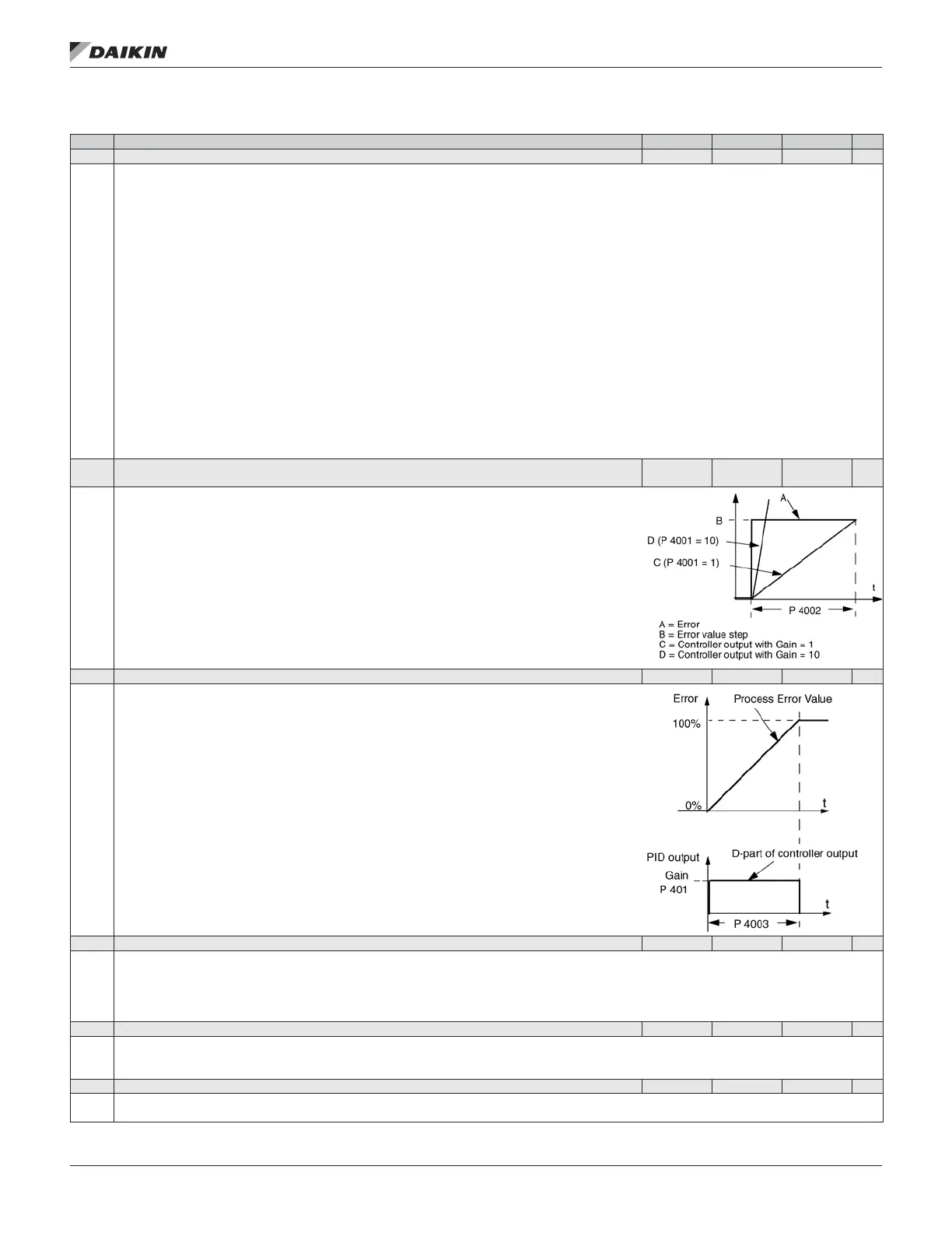
4001 GAIN 0.1… 100.0 0.1 2.5
Denes the PID Controller’s gain.
• The setting range is 0.1… 100.
• At 0.1, the PID Controller output changes one-tenth as much as the error value.
• At 100, the PID Controller output changes one hundred times as much as the error value.
Use the proportional gain and integration time values to adjust the responsiveness of the system.
• A low value for proportional gain and a high value for integral time ensures stable operation, but provides sluggish response.
If the proportional gain value is too large or the integral time too short, the system can become unstable.
Procedure:
• Initially, set:
• 4001 GAIN = 0.1.
• 4002 INTEGRATION TIME = 20 seconds.
• Start the system and see if it reaches the set point quickly while maintaining stable operation. If not, increase GAIN (4001) until the actual signal
(or drive speed) oscillates constantly. It may be necessary to start and stop the drive to induce this oscillation.
• Reduce GAIN (4001) until the oscillation stops.
• Set GAIN (4001) to 0.4 to 0.6 times the above value.
• Decrease the INTEGRATION TIME (4002) until the feedback signal (or drive speed) oscillates constantly. It may be necessary to start and stop
the drive to induce this oscillation.
• Increase INTEGRATION TIME (4002) until the oscillation stops.
• Set INTEGRATION TIME (4002) to 1.15 to 1.5 times the above value.
• If the feedback signal contains high frequency noise, increase the value of Parameter 1303 FILTER AI1 or 1306 FILTER AI2 until the noise
is ltered from the signal.
4002 INTEGRATION TIME
0.0…
3600.0 s
0.1 s 3.0 s
Denes the PID Controller’s integration time. Integration time is, by denition, is the time required
to increase the output by the error value:
• Error value is constant and 100%.
• Gain = 1.
• Integration time of 1 second denotes that a 100% change is achieved in 1 second.
0.0 = NOT SEL – Disables integration (I-part of controller).
0.1…3600.0 = Integration time (seconds).
See 4001 for adjustment procedure.
4003 DERIVATION TIME 0.0… 10.0 s 0.1 s 0.0 s
Denes the PID Controller’s derivation time.
• You can add the derivative of the error to the PID controller output. The derivative is the error value’s
rate of change. For example, if the process error value changes linearly, the derivative is a constant
added to the PID controller output.
• The error-derivative is ltered with a 1- pole lter. The time constant of the lter is dened by parameter
4004 PID DERIV FILTER.
0.0 = NOT SEL – Disables the errorderivative part of the PID controller output
0.1…10.0 = Derivation time (seconds)
4004 PID DERIV FILTER 0.0… 10.0 s 0.1 s 0.1 s
Denes the lter time constant for the error-derivative part of the PID controller output.
• Before being added to the PID controller output, the error-derivative is ltered with a 1-pole lter.
• Increasing the lter time smooths the error-derivative, reducing noise.
0.0 = NOT SEL – Disables the error-derivative lter.
0.1…10.0 = Filter time constant (seconds).
4005 ERROR VALUE INV 0, 1 — 0
Selects either a normal or inverted relationship between the feedback signal and the drive speed.
0 = NO – Normal, a decrease in feedback signal increases drive speed. Error = Ref - Fbk
1 = YES – Inverted, a decrease in feedback signal decreases drive speed. Error = Fbk - Ref
4006 UNITS 0…31 — 4
Selects the unit for the PID controller actual values. (PID1 parameters 0128, 0130, and 0132).
• See parameter 3405 for list of available units.
aCTual sIgnals and parameTers
www.DaikinApplied.com 63 OM 1190-1 • MD4 VFD