Relay Output Control
Using the eldbus for relay output control requires:
• Drive parameter values set as dened below.
• Fieldbus controller supplied reference word(s) in the
appropriate location. (The location is dened by the
Protocol Reference, which is protocol dependent.)
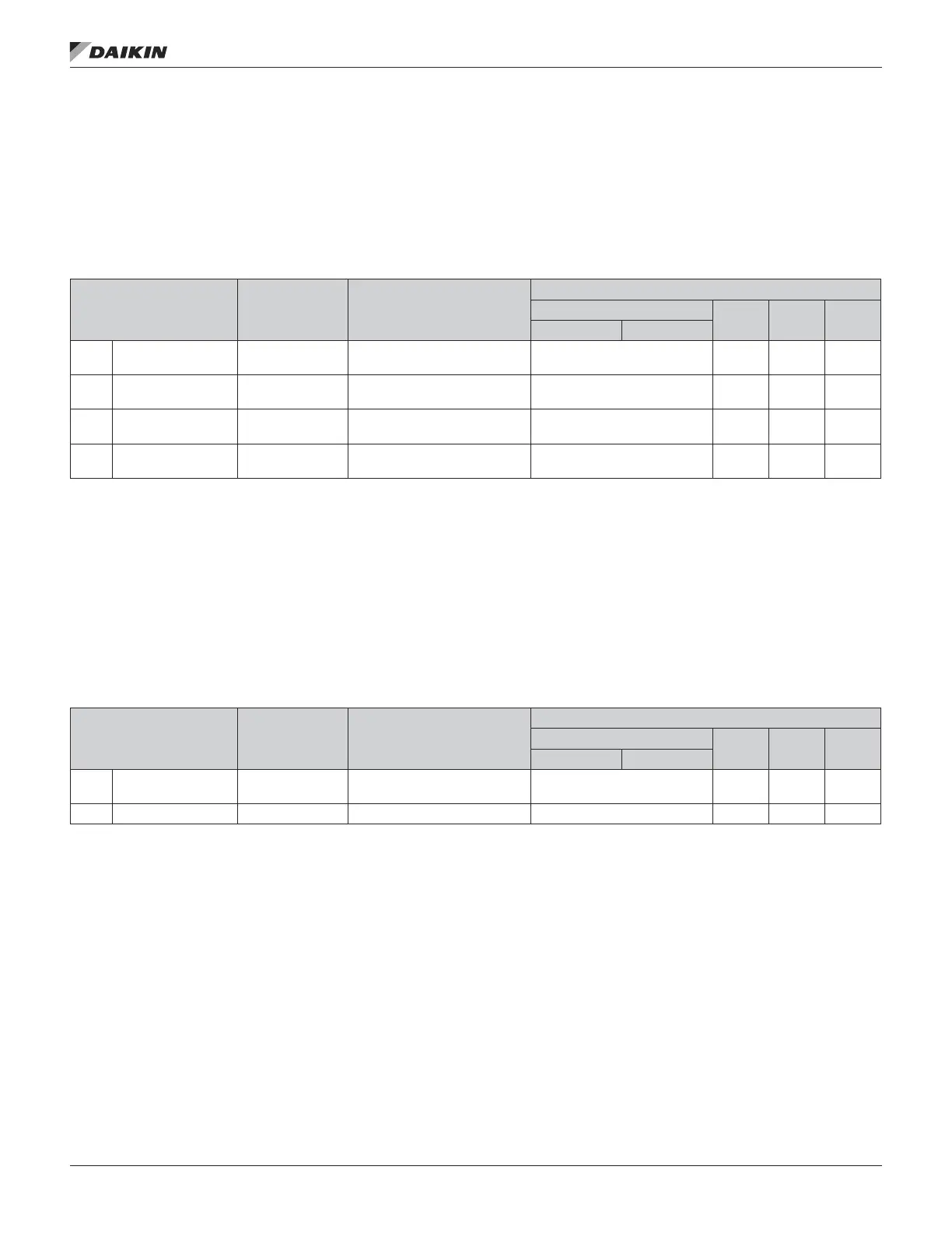
Table 53: Relay Output Control Protocol Reference
Drive Parameter Value Setting
Protocol Reference
Modbus
1
N2 FLN BACnet
abb drv dcu prole
1401 RELAY OUTPUT 1 35 (COMM)
Relay Output 1 controlled by
eldbus.
40134 bit 0 or 00033 BO7 40 BO0
1402
1
RELAY OUTPUT 2 35 (COMM)
Relay Output 2 controlled by
eldbus.
40134 bit 1 or 00034 BO8 41 BO1
1403
1
RELAY OUTPUT 3 35 (COMM)
Relay Output 3 controlled by
eldbus.
40134 bit 2 or 00035 BO9 42 BO2
1410
1
RELAY OUTPUT 4 35 (COMM)
Relay Output 4 controlled by
eldbus.
40134 bit 3 or 00036 BO10 43 BO3
•
1
More than 1 relay requires the addition of a relay extension module
For example: To control relays 1 and 2 using serial communication:
Set parameters 1401 RELAY OUTPUT 1 and 1402 RELAY OUTPUT 1 = 35 (COMM).
Then, for example using N2:
• To turn Relay 1 On: Force object B07 to On.
• To turn Relay 2 On: Force object B08 to On.
• To turn both Relay 1 and 2 On: Force objects B07 and B08 On.
NOTE: Relay status feedback occurs without conguration as dened below.
Table 54: Relay Status Feedback Protocol Reference
Drive Parameter Value Setting
Protocol Reference
Modbus
N2 FLN BACnet
abb drv dcu prole
0122 RO 1-3 STATUS Relay 1…3 status. 40122 0122
BI4…
BI6
76… 78
BI0…
BI2
0123 RO 4 STATUS Relay 4 status. 40123 0123 BI7 79 BI3
fIeldbus ConTrols
www.DaikinApplied.com 77 OM 1190-1 • MD4 VFD