Group 13: Analog Inputs
This group denes the limits and the ltering for analog inputs and are only needed for units shipping without MicroTech controllers
but need eld controls installed.
Table 29: Group 13: Analog Inputs
Code Description Range Resolution Default S
1301 MINIMUM AI1 0.0...100.0% 0.1% 20.0%
Denes the minimum value of the analog input.
• Dene value as a percent of the full analog signal range. See example below.
• The minimum analog input signal corresponds to 1104 REF1 MIN or 1107 REF2 MIN.
• MINIMUM AI cannot be greater than MAXIMUM AI.
• These parameters (reference and analog min. and max. settings) provide scale and offset adjustment for the reference.
• See gure at parameter 1104.
Example: To set the minimum analog input value to 4 mA:
• Congure the analog input for 0…20 mA current signal.
• Calculate the minimum (4 mA) as a percent of full range
(20 mA) = 4 mA / 20 mA * 100% = 20%
1302 MAXIMUM AI1 0.0...100.0% 0.1% 20.0%
Denes the maximum value of the analog input.
• Dene value as a percent of the full analog signal range.
• The maximum analog input signal corresponds to 1105 REF1 MAX or 1108 REF2 MAX.
• See gure at parameter 1104.
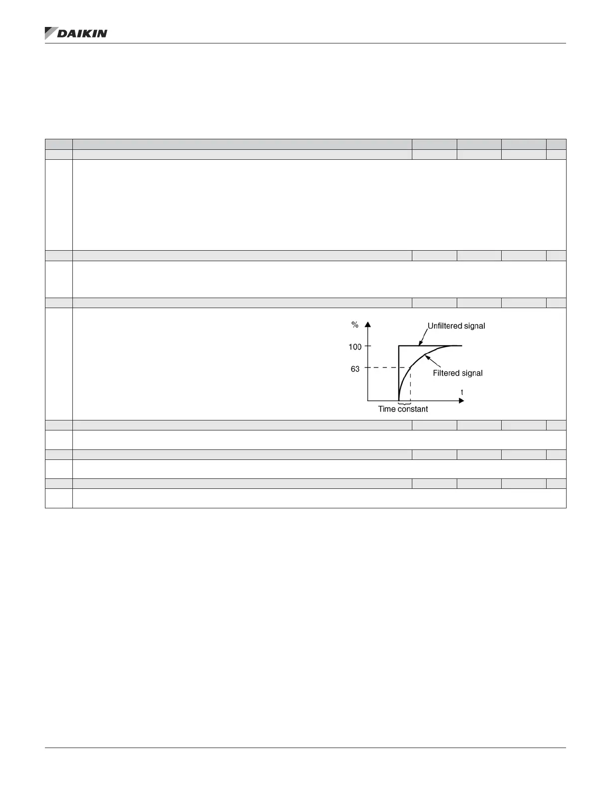
1303 FILTER AI1 0.0...10.0 s 0.1 s 0.1 s
Denes the lter time constant for analog input 1 (AI1).
• The ltered signal reaches 63% of a step change within the time specied.
1304 MINIMUM AI2 0.0...100.0% 0.1% 20.0%
Denes the minimum value of the analog input.
• See MINIMUM AI1 above.
1305 MAXIMUM AI2 0.0...100.0% 0.1% 100.0%
Denes the maximum value of the analog input.
• See MAXIMUM AI1 above.
1306 FILTER AI2 0.0...10.0 s 0.1 s 0.1 s
Denes the lter time constant for analog input 2 (AI2).
• See FILTER AI1 above.
OM 1190-1 • MD4 VFD 44 www.DaikinApplied.com
aCTual sIgnals and parameTers