Group 11: Reference Select
This group denes:
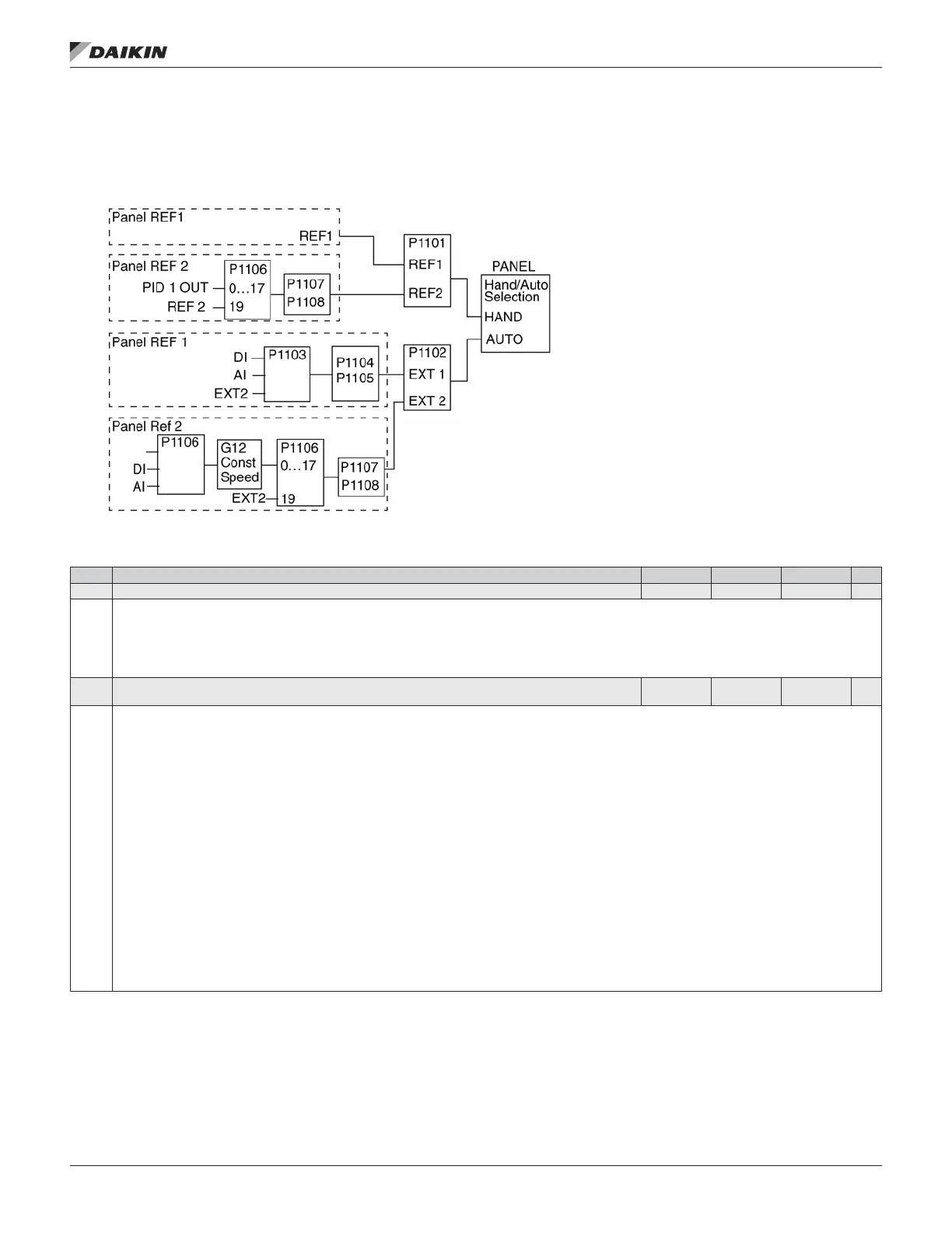
• How the drive selects between command sources.
• Characteristics and sources for REF1 and REF2.
Table 27: Group 11: Reference Select
Code Description Range Resolution Default S
1101 KEYPAD REF SEL 1,2 1 1
Selects the reference controlled in local control mode.
1 = REF1 (Hz/rpm) – Reference type depends on parameter 9904 MOTOR CTRL MODE.
• Speed reference (rpm) if 9904 = 1 (VECTOR: SPEED).
• Frequency reference (Hz) if 9904 = 3 (SCALAR; FREQ).
2 = REF2 (%)
1102 EXT1/EXT2 SEL - 6...12 1 0
Denes the source for selecting between the two external control locations EXT1 or EXT2. Thus, denes the source for Start/Stop/Direction commands and
reference signals.
0 = EXT1 – Selects external control location 1 (EXT1).
• See parameter 1001 EXT1 COMMANDS for EXT1’s Start/Stop/Dir denitions.
• See parameter 1103 REF1 SELECT for EXT1’s reference denitions.
1 = DI1 – Assigns control to EXT1 or EXT2 based on the state of DI1
(DI1 activated = EXT2; DI1 de-activated = EXT1).
2…6 = DI2…DI6 – Assigns control to EXT1 or EXT2 based on the state of the selected digital input. See DI1 above.
7 = EXT2 – Selects external control location 2 (EXT2).
• See parameter 1002 EXT2 COMMANDS for EXT2’s Start/Stop/Dir denitions.
• See parameter 1106 REF2 SELECT for EXT2’s reference denitions.
8 = COMM – Assigns control of the drive via external control location EXT1 or EXT2 based on the eldbus control word.
• Bit 5 of the Command Word 1 (parameter 0301) denes the active external control location (EXT1 or EXT2).
• See Fieldbus user’s manual for detailed instructions.
9 = TIMER 1 – Assigns control to EXT1 or EXT2 based on the state of the Timer
(Timer activated = EXT2; Timer de-activated = EXT1). See Group 36, Timer Functions.
10…12 = TIMER 2… 4 – Assigns control to EXT1 or EXT2 based on the state of the Timer. See Timer 1 above.
-1 = DI1(INV) – Assigns control to EXT1 or EXT2 based on the state of DI1
(DI1 activated = EXT1; DI1 de-activated = EXT2).
-2…-6 = DI2(INV)…DI6(INV) – Assigns control to EXT1 or EXT2 based on the state of the selected digital input. See DI1(INV) above.
aCTual sIgnals and parameTers
www.DaikinApplied.com 39 OM 1190-1 • MD4 VFD