Code Description (continuation of Table 27) Range Resolution Default S
1103 REF1 SELECT 0...21 1 1
Selects the signal source for external reference REF1.
0 = KEYPAD – Denes the control panel as the reference source.
1 = AI1 – Denes analog input 1 (AI1) as the reference source.
2 = AI2 – Denes analog input 2 (AI2) as the reference source.
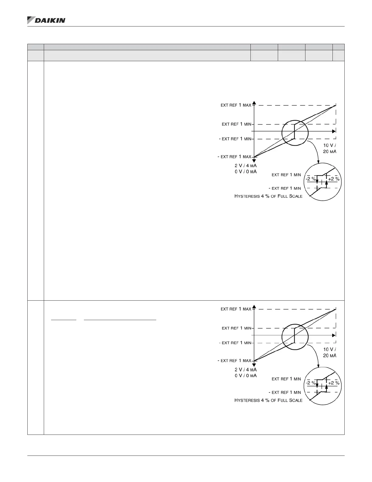
3 = AI1/JOYST – Denes analog input 1 (AI1), congured for joystick operation, as the reference source.
• The minimum input signal runs the drive at the maximum reference in the reverse direction. Dene the minimum using parameter 1104.
• The maximum input signal runs the drive at maximum reference in the forward
direction. Dene the maximum using parameter 1105.
• Requires parameter 1003=3 (request). Warning! Because the low end of the
reference range commands full reverse operation, do not use 0 V as the
lower end of the reference range. Doing so means that if the control signal
is lost (which is a 0 V input) the result is full reverse operation. Instead, use
the following set-up so that loss of the analog input triggers a fault,
stopping the drive:
• Set parameter 1301 MINIMUM AI1 (1304 MINIMUM AI2) at 20% (2 V or 4 mA).
• Set parameter 3021 AI1 FAULT LIMIT to a value 5% or higher.
• Set parameter 3001 AI<MIN FUNCTION to 1 (FAULT).
4 = AI2/JOYST – Denes analog input 2 (AI2), congured for joystick operation, as the
reference source.
• See above (AI1/JOYST) description.
5 = DI3U,4D(R) – Denes digital inputs as the speed reference source (motor
potentiometer control).
• Digital input DI3 increases the speed (the U stands for “up”).
• Digital input DI4 decreases the speed (the D stands for “down”).
• A Stop command resets the reference to zero (the R stands for “reset”).
• Parameter 2205 ACCELER TIME 2 controls the reference signal’s rate of change.
6 = DI3U,4D – Same as above (DI3U,4D(R)), except:
• A Stop command does not reset the reference to zero. The reference is stored.
• When the drive restarts, the motor ramps up (at the selected acceleration rate) to the stored reference.
7 = DI5U,6D – Same as above (DI3U,4D), except that DI5 and DI6 are the digital inputs used.
8 = COMM – Denes the eldbus as the reference source.
9 = COMM+AI1 – Denes a eldbus and analog input 1 (AI1) combination as the reference source. See Analog Input Reference Correction below.
10 = COMM*AI1 – Denes a eldbus and analog input 1 (AI1) combination as the reference source. See Analog Input Reference Correction below.
11 = DI3U, 4D(RNC) – Same as DI3U,4D(R) above, except that:
• Changing the control source (EXT1 to EXT2, EXT2 to EXT1, LOC to REM) does not copy the reference.
12 = DI3U,4D(NC) – Same as DI3U,4D above, except that:
• Changing the control source (EXT1 to EXT2, EXT2 to EXT1, LOC to REM) does not copy the reference.
13 = DI5U,6D(NC) – Same as DI3U,4D above, except that:
• Changing the control source (EXT1 to EXT2, EXT2 to EXT1, LOC to REM) does not copy the reference.
14 = AI1+AI2 – Denes an analog input 1 (AI1) and analog input 2 (AI2) combination as the reference source. See Analog Input Reference Correction below.
15 = AI1*AI2 – Denes an analog input 1 (AI1) and analog input 2 (AI2) combination as the reference source. See Analog Input Reference Correction below.
16 = AI1-AI2 – Denes an analog input 1 (AI1) and analog input 2 (AI2) combination as the reference source. See Analog Input Reference Correction below.
17 = AI1/AI2 – Denes an analog input 1 (AI1) and analog input 2 (AI2) combination as the reference source. See Analog Input Reference Correction below.
Analog Input Reference Correction.
Parameter values 9, 10, and 14…17 use the formula in the following.
Value Setting AI reference is calculated as following:
C + B C value + (B value - 50% of reference value)
C * B C value * (B value / 50% of reference value)
C - B (C value + 50% of reference value) - B value
C / B (C value * 50% of reference value) / B value
Where:
• C = Main Reference value ( = COMM for values 9, 10 and = AI1 for values 14…17).
• B = Correcting reference ( = AI1 for values 9, 10 and = AI2 for values 14…17).
Example:
The gure shows the reference source curves for value settings 9, 10, and 14…17,
where:
• C = 25%.
• P 4012 SETPOINT MIN = 0.
• P 4013 SETPOINT MAX = 0.
• B varies along the horizontal axis.
REF1 SELECT
20 = KEYPAD(RNC) – Denes the control panel as the reference source. A Stop command resets the reference to zero (R stands for reset.). Changing the
control source (EXT1 to EXT2, EXT2 to EXT1) does not copy the reference.
21 = KEYPAD(NC) – Denes the control panel as the reference source. A Stop command does not reset the reference to zero. The reference is stored.
Changing the control source (EXT1 to EXT2, EXT2 to EXT1) does not copy the reference
OM 1190-1 • MD4 VFD 40 www.DaikinApplied.com
aCTual sIgnals and parameTers
 Loading...


