Code Description (continuation of Table 43) Range Resolution Default S
4007 UNIT SCALE 0…4 1 1
Denes the decimal point location in PID controller actual values.
4007 Value Entry Display
0 0003 3
1 0031 3.1
2 0314 3.14
3 3142 3.142
• Enter the decimal point location counting in from the right of the entry.
• See table for example using pi (3.14159).
4008 0 % VALUE
-1000.0…
1000.0%
0.1% 0.0%
Denes (together with the next parameter) the scaling applied to the PID controller’s actual values
(PID1 parameters 0128, 0130, and 0132).
• Units and scale are dened by parameters 4006 and 4007.
4009 100 % VALUE
-1000.0…
1000.0%
0.1% 100%
Denes (together with the previous parameter) the scaling applied to the PID controller’s actual values.
• Units and scale are dened by parameters 4006 and 4007.
4010 SET POINT SEL 0...19 1 0
Denes the reference signal source for the PID controller.
• Parameter has no signicance when the PID regulator is by-passed (see 8121 REG BYPASS CTRL).
0 = KEYPAD – Control panel provides reference.
1 = AI1 – Analog input 1 provides reference.
2 = AI2 – Analog input 2 provides reference.
8 = COMM – Fieldbus provides reference.
9 = COMM + AI1 – Denes a eldbus and analog input 1 (AI1) combination as the reference source. See Analog Input Reference Correction below.
10 = COMM * AI1 – Denes a eldbus and analog input 1 (AI1) combination as the reference source. See Analog Input Reference Correction below.
11 = DI3U, 4D(RNC) – Digital inputs, acting as a motor potentiometer control, provide reference.
• DI3 increases the speed (the U stands for “up”)
• DI4 decreases the reference (the D stands for “down”).
• Parameter 2205 ACCELER TIME 2 controls the reference signal’s rate of change.
• R = Stop command resets the reference to zero.
• NC = Reference value is not copied.
12 = DI3U, 4D(NC) – Same as DI3U, 4D(RNC) above, except:
• Stop command does not reset reference to zero. At restart the motor ramps up, at the selected acceleration rate, to the stored reference.
13 = DI5U, 6D(NC) – Same as DI3U, 4D(NC) above, except:
• Uses digital inputs DI5 and DI6.
14 = AI1 + AI2 – Denes an analog input 1 (AI1) and analog input 2 (AI2) combination as the reference source. See Analog Input Reference Correction below.
15 = AI1 * AI2 – Denes an analog input 1 (AI1) and analog input 2 (AI2) combination as the reference source. See Analog Input Reference Correction below.
16 = AI1 - AI2 – Denes an analog input 1 (AI1) and analog input 2 (AI2) combination as the reference source. See Analog Input Reference Correction below.
17 = AI1/AI2 – Denes an analog input 1 (AI1) and analog input 2 (AI2) combination as the reference source. See Analog Input Reference Correction below.
19 = INTERNAL – A constant value set using parameter 4011 provides reference.
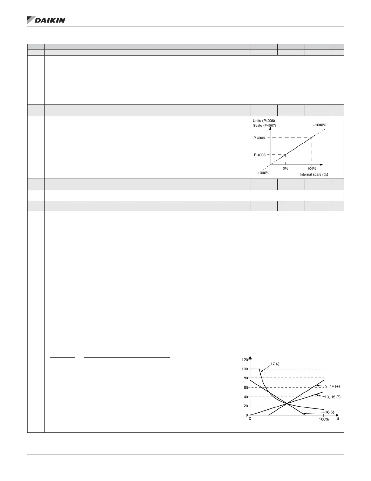
Analog Input Reference Correction
Parameter values 9, 10, and 14…17 use the formula in the following table.
Value Setting AI reference is calculated as following:
C + B C value + (B value - 50% of reference value)
C * B C value * (B value / 50% of reference value)
C - B (C value + 50% of reference value) - B value
C / B (C value * 50% of reference value) / B value
Where:
• C = Main Reference value ( = COMM for values 9, 10 and = AI1 for values 14…17).
• B = Correcting reference ( = AI1 for values 9, 10 and = AI2 for values 14…17).
Example: The gure shows the reference source curves for value settings 9, 10, and 14…17, where:
• C = 25%.
• P 4012 SETPOINT MIN = 0.
• P 4013 SETPOINT MAX = 0.
• B varies along the horizontal axis.
20 = PID2OUT – Denes PID controller 2 output (parameter 0127 PID 2 OUTPUT) as the reference source.
OM 1190-1 • MD4 VFD 64 www.DaikinApplied.com
aCTual sIgnals and parameTers