Table 41: Group 35: Motor Temp Meas
Code Description Range Resolution Default S
3501 SENSOR TYPE 0…6 1 0
Identies the type of motor temperature sensor used, PT100 (°C) or PTC (ohms).
See parameters 1501 and 1507, page 45.
0 = NONE
1 = 1 × PT100 – Sensor conguration uses one PT 100 sensor.
• Analog output AO1 or AO2 feeds constant current through the sensor.
• The sensor resistance increases as the motor temperature rises, as does the voltage over the sensor.
• The temperature measurement function reads the voltage through analog input AI1 or AI2 and converts
it to degrees centigrade.
2 = 2 × PT100 – Sensor conguration uses two PT 100 sensors.
• Operation is the same as for above 1 x PT100.
3 = 3 × PT100 – Sensor conguration uses three PT 100 sensors.
• Operation is the same as for above 1 x PT100.
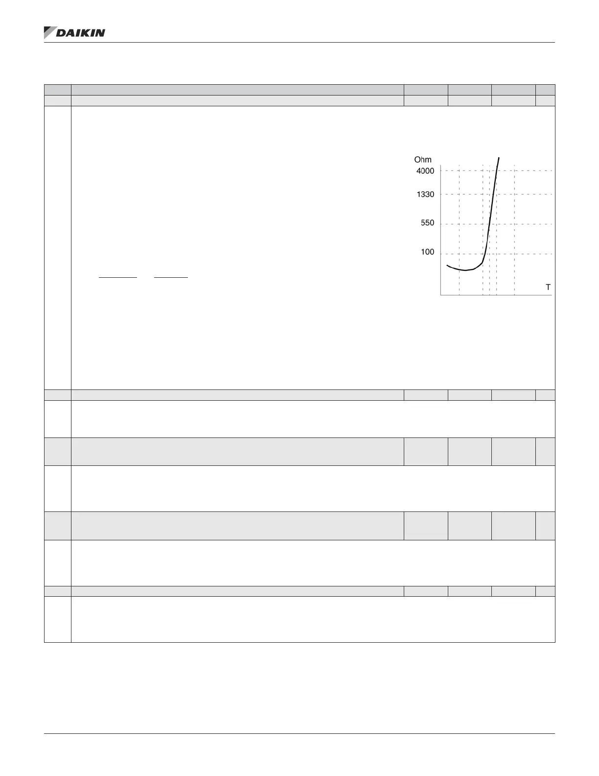
4 = PTC – Sensor conguration uses one PTC.
• The analog output feeds a constant current through the sensor.
• The resistance of the sensor increases sharply as the motor temperature rises over the PTC reference
temperature (Tref), as does the voltage over the resistor. The temperature measurement function reads
the voltage through analog input AI1 and converts it into ohms.
• The gure shows typical PTC sensor resistance values as a function of the motor operating temperature.
Temperature Resistance
Normal 0 … 1.5 kohm
Excessive > 4 kohm
5 = THERMISTOR (0) – Sensor conguration uses a thermistor.
• Motor thermal protection is activated through a digital input. Connect either a PTC sensor or a normally closed thermistor relay to a digital input.
The drive reads the digital input states as shown in the above table.
• When the digital input is ‘0’ the motor is overheated.
• See the gures in the introduction to this Group.
6 = THERMISTOR (1) – Sensor conguration uses a thermistor.
• Motor thermal protection is activated through a digital input. Connect a normally open thermistor relay to a digital input. The drive reads the digital input
states as shown in the above table.
• When the digital input is ‘1’ the motor is overheated.
See the gures in the introduction to this Group
3502 INPUT SELECTION 1…8 1 1
Denes the input used for the temperature sensor.
1 = AI1 – PT100 and PTC.
2 = AI2 – PT100 and PTC.
3…8 = DI1…DI6 – Thermistor
3503 ALARM LIMIT
-10...200°C/
0...5000
Ohm/ 0…1
1
-110°C/
1500 Ohm/
0
Denes the alarm limit for motor temperature measurement.
• At motor temperatures above this limit, the drive displays an alarm (2010, MOTOR OVERTEMP)
For thermistors:
0 = de-activated
1 = activated
3504 FAULT LIMIT
-10...200°C/
0...5000
Ohm/ 0…1
1
-130°C/
4000 Ohm/
0
Denes the fault limit for motor temperature measurement.
• At motor temperatures above this limit, the drive displays a fault (9, MOTOR OVERTEMP) and stops the drive.
For thermistors:
0 = de-activated
1 = activated
3505 AO EXCITATION 0
Enables current feed from analog output AO. Parameter setting overrides parameter Group 15 ANALOG OUTPUTS settings, page 45.
With PTC the output current is 1.6 mA.
With Pt 100 the output current is 9.1 mA.
0 = disabled
1 = enabled
OM 1190-1 • MD4 VFD 60 www.DaikinApplied.com
aCTual sIgnals and parameTers