Code Description (continuation of Table 37) Range Resolution Default S
3008 ZERO SPEED LOAD 25…150% 1 70%
Sets the maximum allowable current at zero speed.
• Value is relative to 9906 MOTOR NOM CURR
3009 BREAK POINT FREQ 1…250 Hz 1 35 Hz
Sets the break point frequency for the motor load curve.
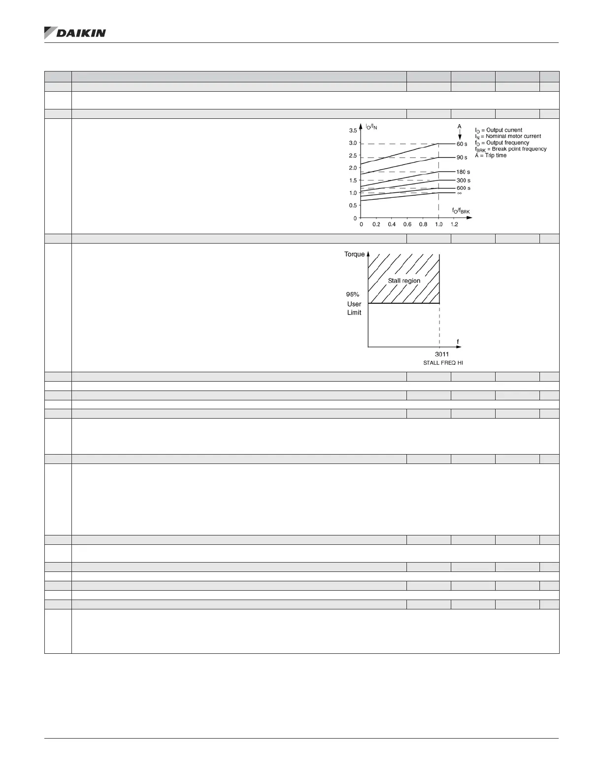
Example: Thermal protection trip times when parameters 3006 MOT THERM TIME,
3007 MOT LOAD CURVE and 3008 ZERO SPEED LOAD have default values.
3010 STALL FUNCTION 0…2 1 35 Hz
This parameter denes the operation of the Stall function. This protection is active if
the drive operates in the stall region (see gure) for the time dened by 3012 STALL
TIME. The “User Limit” is dened in Group 20 by 2017 MAX TORQUE 1, 2018 MAX
TORQUE 2, or the limit on the COMM input.
0 = NOT SEL – Stall protection is not used.
1 = FAULT – When the drive operates in the stall region for the time set by
3012 STALL TIME:
• The drive coasts to stop.
• A fault indication is displayed.
2 = WARNING – When the drive operates in the stall region for the time set by
3012 STALL TIME:
• A warning indication is displayed.
• The warning disappears when the drive is out of the stall region for half
the time set by parameter 3012 STALL TIME.
3011 STALL FREQUENCY 0.5…50.0 Hz 0.1 Hz 20.0 Hz
This parameter sets the frequency value for the Stall function. Refer to Figure.
3012 STALL TIME 10…400 s 1 s 20 s
This parameter sets the time value for the Stall function.
3017 EARTH FAULT 0…1 1 1
Denes the drive response if the drive detects a ground fault in the motor or motor cables. The drive monitors for ground faults while the drive is running, and
while the drive is not running. Also see parameter 3023 WIRING FAULT.
0 = DISABLE – No drive response to ground faults.
1 = ENABLE – Ground faults display fault 16 (EARTH FAULT), and (if running) the drive coasts to stop.
3018 COMM FAULT FUNC 0…3 1 0
Denes the drive response if the eldbus communication is lost.
0 = NOT SEL – No response.
1 = FAULT – Displays a fault (28, SERIAL 1 ERR) and the drive coasts to stop.
2 = CONST SP7 – Displays a warning (2005, IO COMM) and sets speed using 1208 CONST SPEED 7. This “alarm speed” remains active until the eldbus
writes a new reference value.
3 = LAST SPEED – Displays a warning (2005, IO COMM) and sets speed using the last operating level. This value is the average speed over the last 10
seconds. This “alarm speed” remains active until the eldbus writes a new reference value.
Caution: If you select CONST SP7, or LAST SPEED, make sure that continued operation is safe when eldbus communication is lost.
3019 COMM FAULT TIME
0.0…60.0 s 0.1 s 10.0 s
Sets the communication fault time used with 3018 COMM FAULT FUNC.
• Brief interruptions in the eldbus communication are not treated as faults if they are less than the COMM FAULT TIME value.
3021 AI1 FAULT LIMIT 0.0…100.0% 0.1% 0.0%
Sets a fault level for analog input 1. See 3001 AI<MIN FUNCTION.
3022 AI2 FAULT LIMIT 0.0…100.0% 0.1% 0.0%
Sets a fault level for analog input 2. See 3001 AI<MIN FUNCTION.
3023 WIRING FAULT 0, 1 1 1
Denes the drive response to cross wiring faults and to ground faults detected when the drive is NOT running. When the drive is not running it monitors for:
• Improper connections of input power to the drive output (the drive can display fault 35, OUTPUT WIRING if improper connections are detected).
• Ground faults (the drive can display fault 16, EARTH FAULT if a ground fault is detected). Also, see parameter 3017 EARTH FAULT.
0 = DISABLE – No drive response to either of the above monitoring results.
1 = ENABLE – The drive displays faults when this monitoring detects problems.
OM 1190-1 • MD4 VFD 54 www.DaikinApplied.com
aCTual sIgnals and parameTers

 Loading...


