(continuation of Table 68)
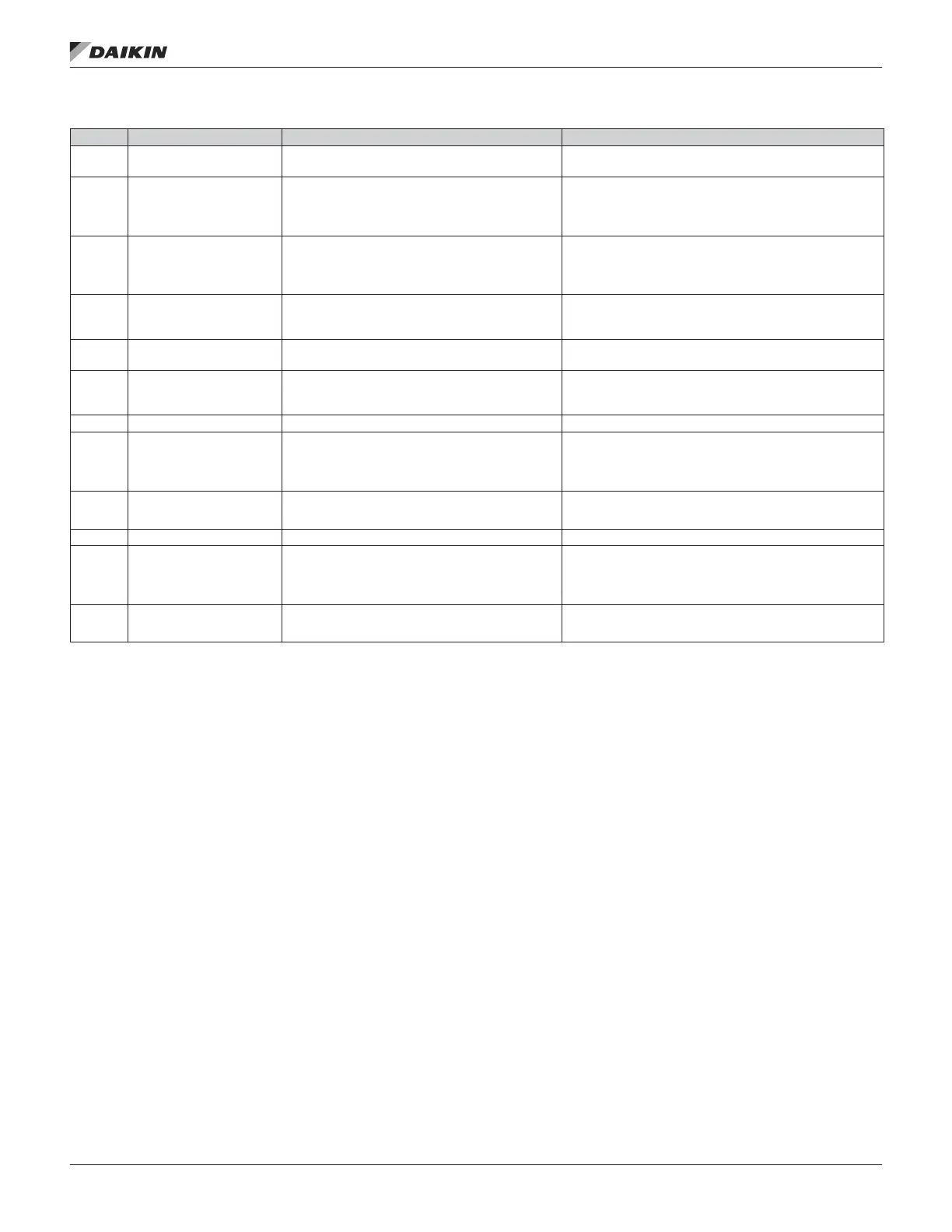
CODE ALARM CAUSE WHAT TO DO
2018 1) PID SLEEP 3009 bit 1 Sleep function has entered sleeping mode.
See parameter Group 40: Process PID Set 1 (page 62)…
Group 41: Process PID Set 2 (page 66).
2021
START ENABLE 1 MISSING
3009 bit 4
No Start Enable 1 signal received
Check parameter 1608 START ENABLE 1 settings.
Check digital input connections.
Check eldbus communication settings.
2022
START ENABLE 2 MISSING
3009 bit 5
No Start Enable 2 signal received
Check parameter 1609 START ENABLE 2 settings.
Check digital input connections.
Check eldbus communication settings.
2023
EMERGENCY STOP 3009
bit 6
Drive has received emergency stop command and
ramps to stop according to ramp time dened by
parameter 2208 EMERG DEC TIME.
Check that it is safe to continue operation.
Return emergency stop push button to normal position.
2025 FIRST START 3009 bit 8
Motor identication magnetization is on. This alarm
belongs to normal start-up procedure.
Wait until drive indicates that motor identication is completed.
2027
USER LOAD CURVE 3009
bit 10
Condition dened by 3701 USER LOAD C MODE has
been valid longer than half of the time set by 3703
USER LOAD C TIME.
See parameter Group 37: User Load Curve, page 61.
2028 START DELAY 3009 bit 11 Start delay in progress See parameter 2113 START DELAY, page 42.
2030 INLET LOW 3009 bit 13 Pressure at pump/fan inlet too low
Check for a closed valve on the inlet side of the pump/fan.
Check piping for leaks.
See parameter Group 44: Pump Protection, page 66.
2031 OUTLET HIGH 3009 bit 14 Pressure at pump/fan outlet too high
Check piping for blocks.
See parameter Group 44: Pump Protection, page 66.
2032 PIPE FILL 3009 bit 15 Pipe ll in progress See parameters 4421…4426, page 66.
2033 INLET VERY LOW 0310 bit 0 Pressure at pump/fan inlet too low
Check for a closed valve on the inlet side of the pump/fan.
Check piping for leaks.
See parameter Group 44: Pump Protection, page 66.
2034
OUTLET VERY HIGH 0310
bit 1
Pressure at pump/fan outlet too high
Check piping for blocks.
See parameter Group 44: Pump Protection, page 66.
1) Even when the relay output is congured to indicate alarm conditions (e.g. parameter 1401 RELAY OUTPUT 1 = 5 (ALARM) or 16 (FLT/ALARM)), this alarm is not
indicated by a relay output.
OM 1190-1 • MD4 VFD 92 www.DaikinApplied.com
faulT TraCIng
 Loading...


