DF4910HD-DN | DDF4910HDV-DN-IM/-SM
www.dallmeier.com 29
Step 4
Connect the required cables to the connectors of the camera module
(see Fig. 5-7 and chapter “Pin Assignment” on page 97).
If necessary, connect a CVBS monitor to the video preview output (Fig. 5-4).
If PoE (Power over Ethernet) is not available, rst connect the camera to a suitable
power supply unit and then connect the power supply unit to the mains socket.
Carefully remove the foam ring with the ambient light sensor (Fig. 5-7) from the lens.
Be careful not to tear or bend the cables.
Align the camera with your scene using the 3-axis mount and set the focal length and
focus (loosen the corresponding locking screws before making any adjustments and
tighten them again when nished).
Attach the foam ring back onto the lens while ensuring that the ambient light sensor will
not be covered by the black inner dome cover.
Disconnect the CVBS monitor from the video preview output.
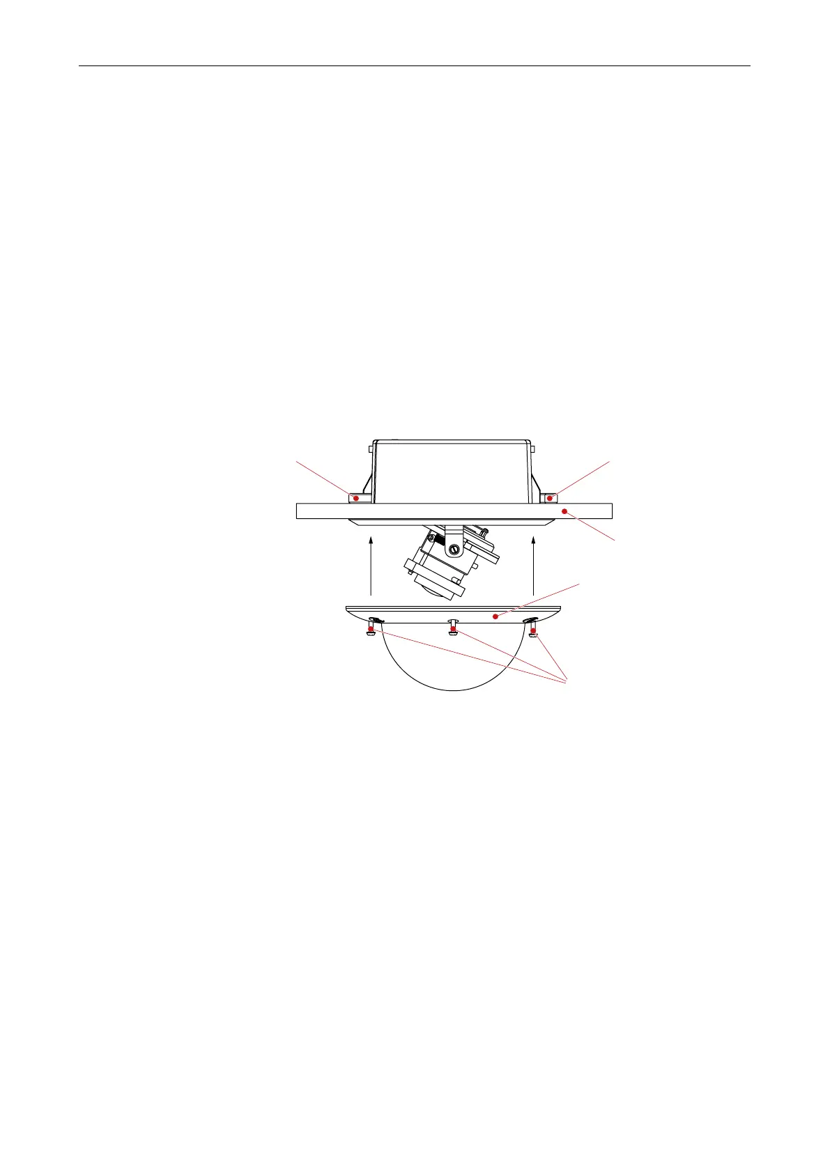
Attach the trim ring to the housing and tighten the 3 housing screws using a T20 torx
wrench.
Housing screw
(T20 Torx)
Locked ceiling clampLocked ceiling clamp
Suspended ceiling
Trim ring with bubble
Fig. 6-6
6.2.2 Surface Mount Variant (SM)
The housing base is mounted with 3 screws (Ø 4 mm) to the ceiling/wall.
You need:
• T20 torx wrench
• Marking tool (e.g. awl)
• 3 mounting screws (Ø 4 mm)
• 3 anchors
• Electric drill
• Screwdriver