40
Xtium-CLHS PX8 Reference Xtium-CLHS PX8 User's Manual
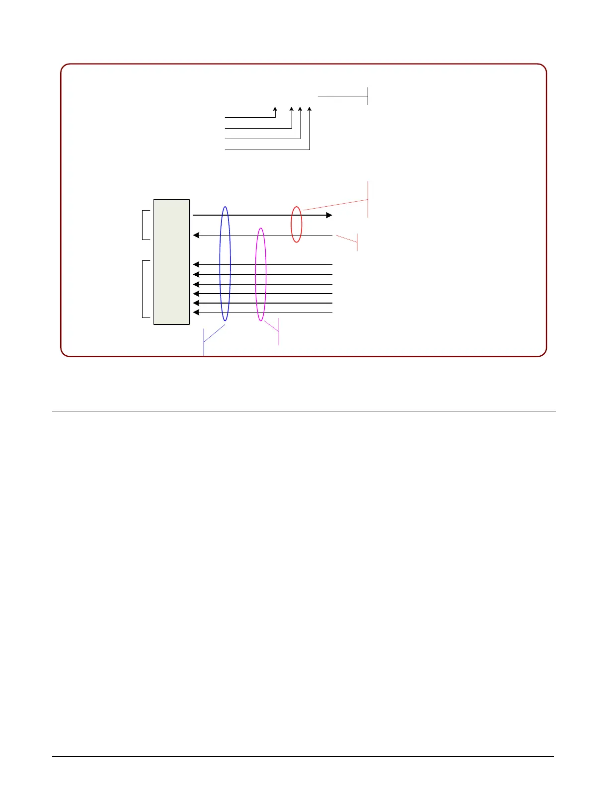
Xtium CLHS PX
8
C2
,
7M
1
One Command Channel
Protocol Supported
7
Lanes Max
Copper Connection
Single Connector
T
xC
RxC
Rx
1
Rx
2
Rx3
Rx
4
Rx
5
Rx6
Forms a
Minimal
Camera
Connection
Additional
Data Lanes
for
Supported
Cameras
Command Channel
to
/
from
the Camera
This is also Data Lane
0 from the Camera
Video Channel uses
1 to
7
Lanes as output by the camera
.
The more Lanes used by a camera
, the greater is the video bandwidth
.
The “Link” is the camera command
channel plus the
1
to
7
Lanes used
.
J3
Camera Link HS
Figure 15:CLHS Camera Interface
Line Trigger Source Selection for Line scan
Applications
Line scan imaging applications require some form of external event trigger to synchronize line scan
camera exposures to the moving object. This synchronization signal is either an external trigger
source (one exposure per trigger event) or a shaft encoder source composed of a single or dual
phase (also known as a quadrature) signal.
The Xtium-CLHS PX8 shaft encoder inputs provide additional functionality with pulse drop, pulse
multiply, and pulse direction support.
The following table describes the line-trigger source types supported by the Xtium-CLHS PX8. Refer
to the Sapera Acquisition Parameters Reference Manual (OC-SAPM-APR00) for descriptions of the
Sapera parameters.