64
Technical Specifications Xtium-CLHS PX8 User's Manual
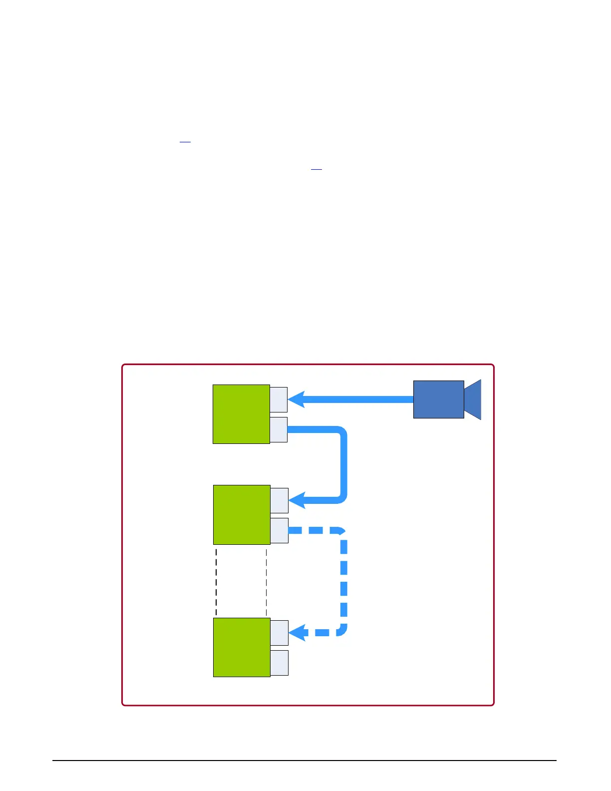
Data Forwarding Setup
Distributed processing of high bandwidth image data is easily configured by inter-connecting
multiple Xtium-CLHS boards. The following description and block diagram shows the simple
physical setup. The user has total control to the actual distributed processing task divisions and
algorithms.
Connect a camera to J3
of the first Xtium-CLHS board installed in the first PC. This board is
defined as the “Data Forwarding Master”.
Using a second Camera Link HS cable, connect J2 of the Data Forwarding Master Xtium-CLHS
board to J3 of second Xtium-CLHS installed in a separate computer or the same as the first
Xtium if it can manage the processing. This second board is defined as the “Data Forwarding
Slave #1”.
Camera Link HS cables used to interconnect Xtium-CLHS boards could be up to 15 meters.
Optionally, the J2 connector of the Data Forwarding Slave #1 Xtium-CLHS board can connect to
J3 of a third Xtium-CLHS (“Data Forwarding Slave #2”).
The number of Data Forwarding Slave boards should not exceed 5, for a total of 6 boards. The
Xtium CLHS boards can either have separate computers or share computers dependent on the
distributed processing requirements.
The Xtium-CLHS driver will automatically detect whether a board is connected to a camera
(becoming the Data Forwarding Master) or is connected to forwarded data (becoming a Data
Forwarding Slave).
Each Data Forwarding Slave board has full control of the camera data portion transferred to the
host computer for processing.
CLHS
High Bandwidth
Camera
Xtium-CLHS
#1
J3
J2
Xtium-CLHS
#2
J3
J2
Xtium-CLHS
#6
J3
J2
CLHS Cable
CLHS Cable
CLHS Cable(s)
Data
Forwarding
Master
Data Forwarding
Slave #1
Data Forwarding
Slave #5
Figure 22: Data Forwarding Block Diagram