Xtium-CLHS PX8 User's Manual Technical Specifications
75
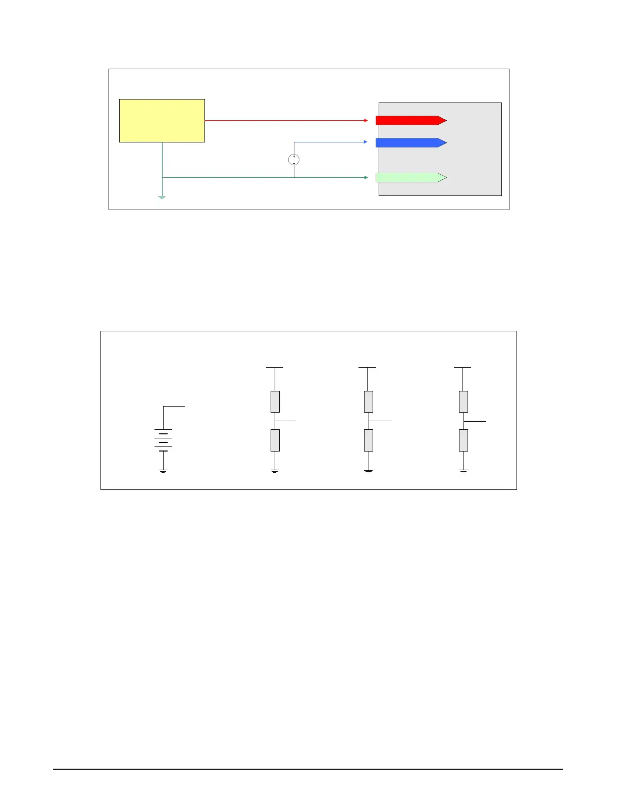
Example: Connecting a TTL Shaft Encoder to RS-422 Inputs
RS-422 (+) input
RS-422 (-) input
FG/system GND
DC
Bias Voltage
+1V to +2V
TTL signal source
GND
Frame Grabber System
Connecting TTL Signals to
RS-422 Inputs
Figure 30: Connecting TTL to RS-422 Shaft Encoder Inputs
• RS-422 (-) input is biased to a DC voltage from +1 to +2 volts.
• This guarantees that the TTL signal connected to the RS-422 (+) input will be detected as a
logic high or low relative to the (-) input.
• The TTL shaft encoder ground, the bias voltage ground, and the Xtium-CLHS PX8 computer
system ground must be connected together.
Example for Generating a RS-422 (-) Input Bias Source
330
220
+5V
+2V
680
100
+12V
+1.5V
+1.5V
Battery
2.2K
150
+24V
+1.5V
Examples on Generating a DC voltage for the RS-422 (-) Input
Figure 31: Generating a DC Bias Voltage
• DC voltage for the RS-422 (-) input can be generated by a resister voltage divider.
• Use a single battery cell if this is more suitable to your system.