70
Technical Specifications Xtium-CLHS PX8 User's Manual
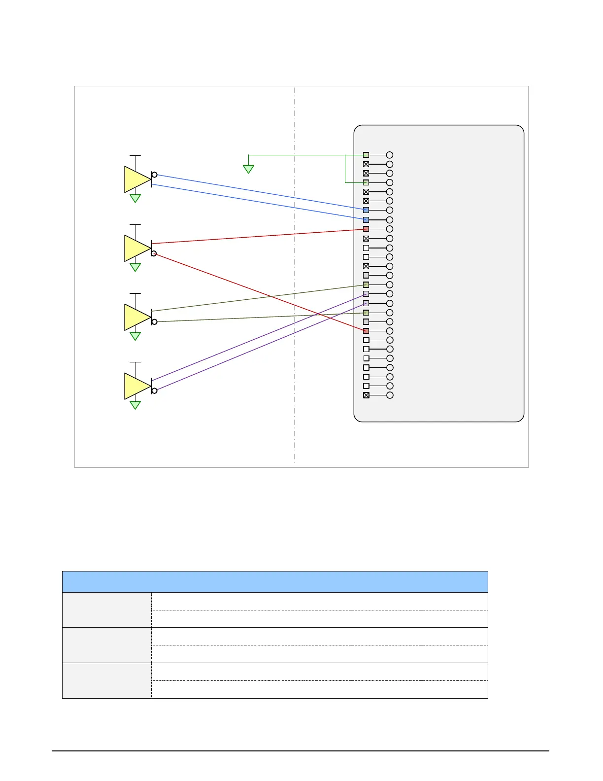
Block Diagram: Connecting External Drivers to General Inputs on J1
J1:
External Signals Connector
(DH
60-27
P)
Reserved
4
External Signals Xtium
-CL
HS
PX
8
26
27
:
:
V (+)
3
V
(+)
2
V (+)
1
V
(+)
Differential
Driver
User Signal
Ground
25 :
24 :
23 :
General Output 422 :
General Output 321
:
19
20
:
:
18 :
17
:
General Input 4 (+)
16 :
General Input
3 (+)15 :
Power Output (
12 Volts)
14
:
Ground
13
:
General Output
212 :
General Output 1
/
Strobe11 :
Ground10 :
General Input 2 / Trigger 2 (+)9
:
General Input 1 / Trigger 1 (+)8 :
7 :
Shaft Encoder B (+)6 :
Shaft Encoder B (
-
)5 :
Ground4 :
Shaft Encoder A (+)3 :
Shaft Encoder A (-)2 :
Ground1
:
Differential
Driver
Differential
Driver
Differential
Driver
General Input
1
/ Trigger 1 (-)
General Input 4
(-)
General Input
3 (-)
Power Output (
5 Volts)
General Input 2
/ Trigger 2
(-)
General Output
5
General Output 6
General Output 7
General Output 8
Figure 25:External Signals Connection Diagram
External Driver Electrical Requirements
The Xtium-CLHS allows user selected (software programmable) input switching points to support
RS-422, TTL, 12V or 24V input signals. The following table defines the external signal voltage
requirements from the driver circuits connected to the Xtium external inputs.
Input Level Description MIN MAX
TTL/RS-422
Output Voltage High (V
OH
)
2.4 V 5.5 V
Output Voltage Low (V
OL
)
0 V 0.8 V
12V
Output Voltage High (V
OH
)
9 V 13.2 V
Output Voltage Low (V
OL
)
0 V 3 V
24V
Output Voltage High (V
OH
)
18 V 26.4 V
Output Voltage Low (V
OL
)
0 V 6 V