62
Technical Specifications Xtium-CLHS PX8 User's Manual
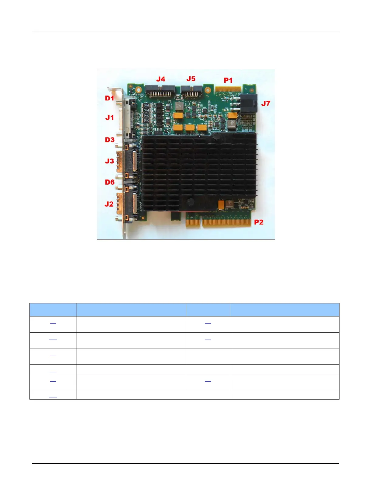
Connector and Switch Locations
Xtium-CLHS PX8 Board Layout Drawing
Figure 20: Board Layout
Connector / LED Description List
The following table lists components on the Xtium-CLHS PX8 board. Detailed information
concerning the connectors/LEDs follows this summary table.
Location Description Location Description
J1 External I/O Signals connector
(DH60-27P)
J5 Multi Board Sync
D1 Boot-up/PCIe Status LED
(refer to text)
J7 PC power to J1
J3 Camera Link HS Input Connector P2 PCIe x8 computer bus connector
(Gen2 compliant slot preferred)
D3 Camera Link HS status LED P1 Reserved
J4 Internal I/O Signals connector
(26-pin SHF-113-01-L-D-RA)
J2 Camera Link HS Output Connector
(used for Data Forwarding)
D6 Data Forwarding status LED
Table 22: Board Connector List