42
Xtium-CLHS PX8 Reference Xtium-CLHS PX8 User's Manual
K
D
D
K
D
D
K
D
D
K
D
D
K
D
D
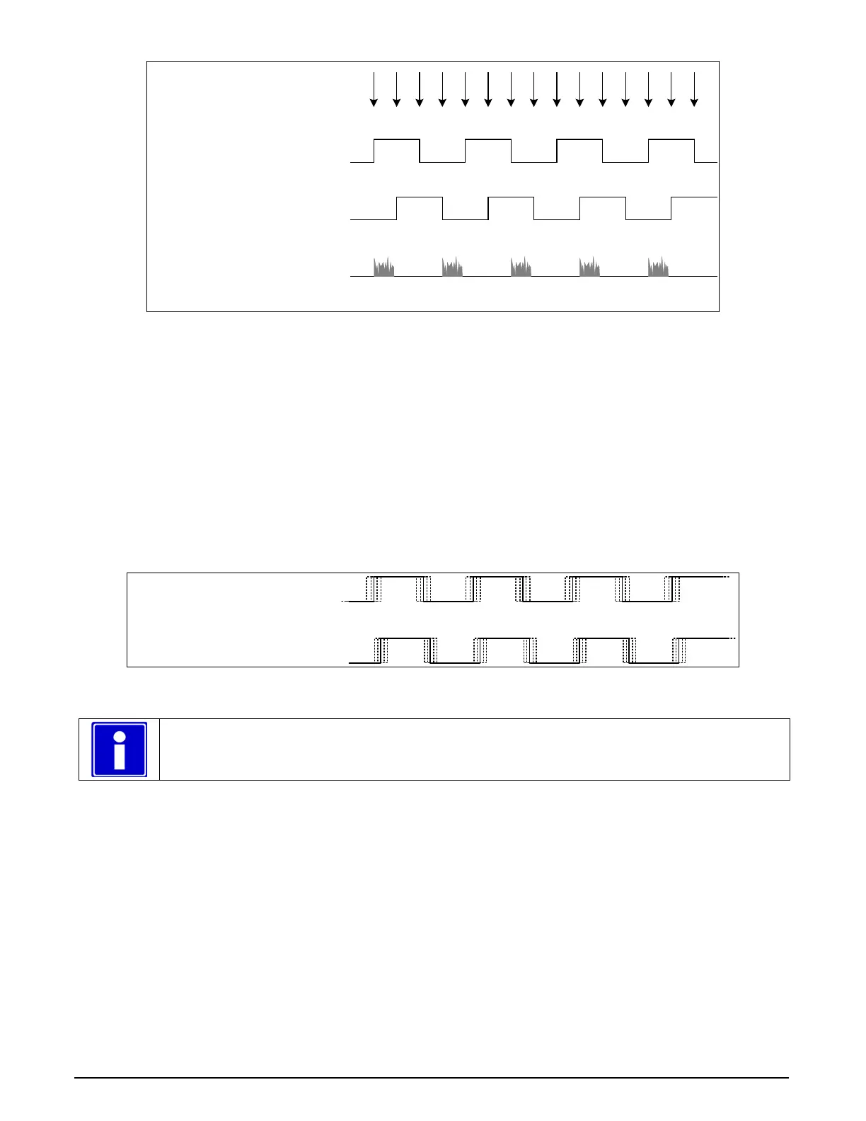
Shaft Encoder phase A
Shaft Encoder phase B
K = Keep
D = Drop or Skip
Note: in this example, Number of trigger to drop = 2
Line acquired
Figure 16: Encoder Input with Pulse-drop Counter
Example using Sequential Encoder Input
Support of a dual phase encoder should consider the direction of motion of one phase signal to the
other. Such a case might exist where system vibrations and/or conveyor backlash can cause the
encoder to briefly travel backwards. The acquisition device must in those cases count the reverse
steps and subtract the forward steps such that only pulses after the reverse count reaches zero are
considered. By using the event “Shaft Encoder Reverse Counter Overflow”, an application can
monitor an overflow of this counter.
The example figure below shows shaft encoder signals with high jitter. If the acquisition is
triggered when phase B follows phase A, with jitter present phase B may precede phase A. Use of
the Shaft Encoder Direction parameter will prevent false trigger conditions.
Shaft Encoder phase A
Shaft Encoder phase B
Figure 17: Using Shaft Encoder Direction Parameter
Note: Modify camera file parameters easily with the Sapera CamExpert program.
CVI/CCF File Parameters Used
Shaft Encoder Enable = X, where:
• If X = 1, Shaft Encoder is enabled
• If X = 0, Shaft Encoder is disabled
Shaft Encoder Pulse Drop = X, where:
• X = number of trigger pulses ignored between valid triggers
Shaft Encoder Pulse Multiply = X, where:
• X = number of trigger pulses generated for each shaft encoder pulses
Shaft Encoder Pulse Drop/Multiply Order = X, where:
• If X = 1, the drop operation will be done first, followed by the multiplier operation
• If X = 0 or 2, the multiplier operation will be done first, followed by the drop operation