130 AK2-SC 255 Reference Manual RS.8D.M1.22
Alarms for
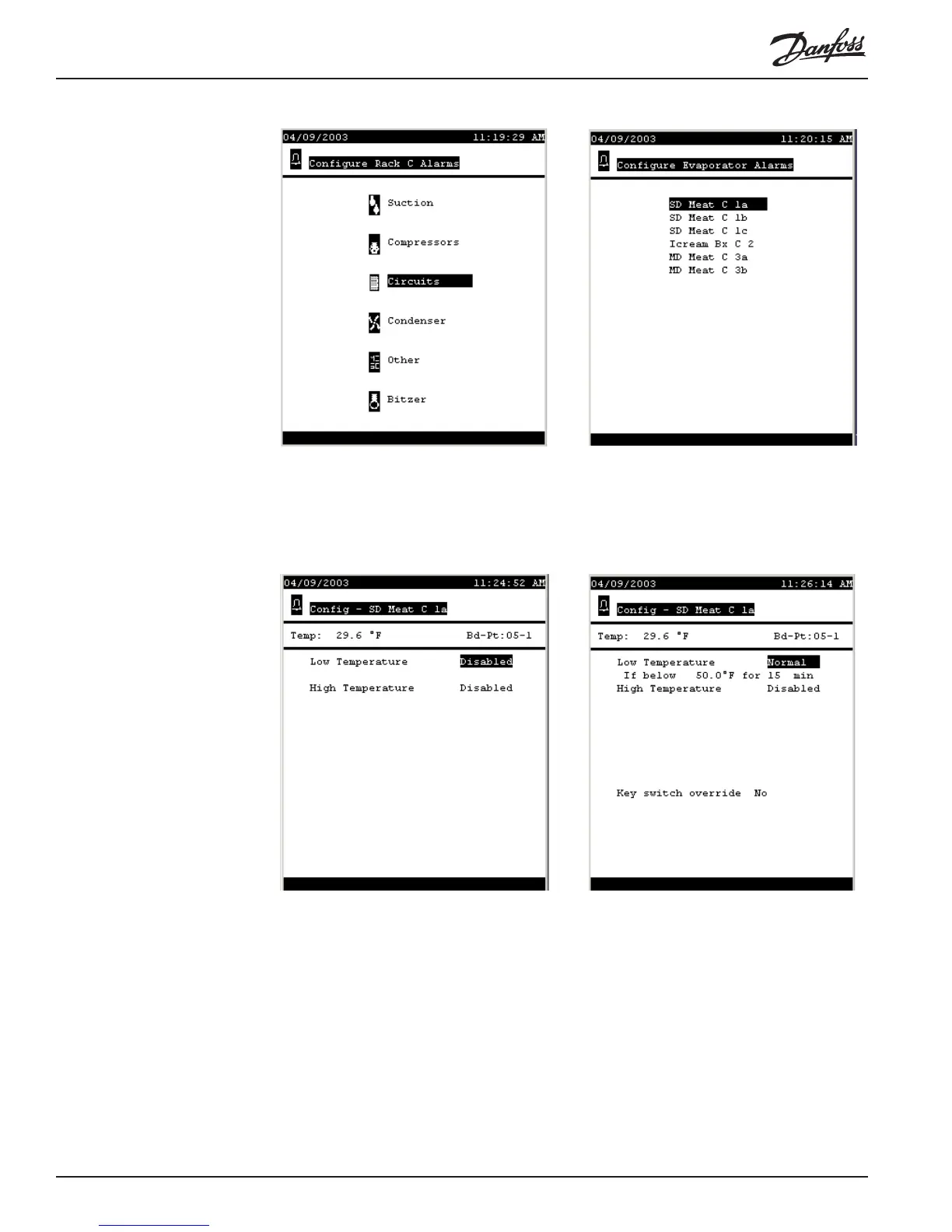
AK2-SC 255 circuits Select the first circuit on the list above. It turns out to be typical for circuits controlled
directly by the SC 255. Initially, the alarm screen looks as at left below.
Notice that the name of the circuit appears in the heading of the screen. Then there is
an area where the current sensor temperature appears, along with the number of the
I/O board and point to which the case temperature sensor is wired. At first, you see
two alarms, both disabled.
In the screen at right above, we have enabled one of the alarms by changing its level
to Normal. We have changed the default settings, 50° and 30 min, to more reasonable
settings for the fixture. Enabling the alarm also caused the appearance further down
the screen of a question about a Key switch override.
The following screens show the second alarm configured, and the key switch override