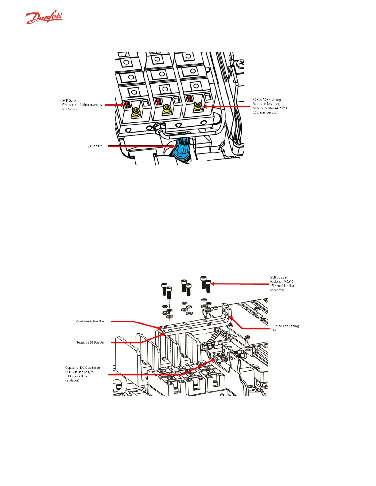
Figure 4-163 SCR Orientation - TTS300/TGS230
6. PlacethenegativebusbarontheSCRs.ThenegativebusbarshouldbenexttotheSCRGate
Connectors(alignedwiththeholesidentifiedas#3ontheSCRs).RefertoFigure4-164BusBar
Installation-TTS300/TGS230andFigure4-165BusBarLocations-TTS300/TGS230onpage155.
7. Installthepositivebusbarbesidethenegativebusbar(alignedwithholesidentifiedas#2onthe
diodes).
8. Thecurvedsectionofthebusbarshouldbeinstalledupwards.RefertoFigure4-164BusBar
Installation-TTS300/TGS230.
9. Insertandfinger-tightenthesix(6)M6x16BusBarfasteners.RefertoSection4.15.1SCRDCBusBar
RemovalandInstallationonpage126forthisandthefollowingstep.
10. Insertandfinger-tightenthetwo(2)M6x20BusBarboltsandM6nutstosecuretheSCRBusBarstothe
CapacitorDCBusBar.
Figure 4-164 Bus Bar Installation - TTS300/TGS230
Page 154 of 294 - M-SV-001-EN Rev. H 1/23/2023