Motor cable length, m (ft)
dv/dt (kV/µs)
0
100
(328)
200
(656)
0.50
1.00
1.50
2.00
2.50
3.00
3.50
300
(984)
e30bu006.10
1
2
3
4
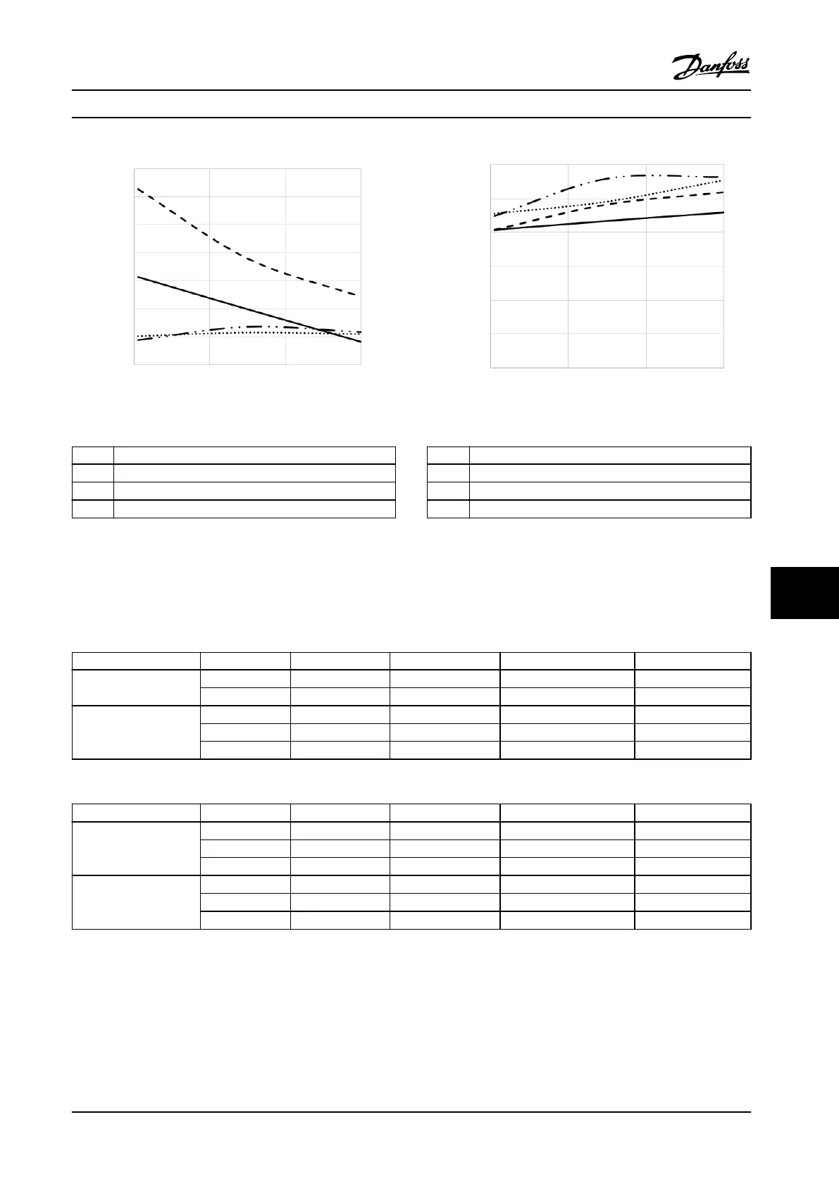
1 Shielded cable with no lter
2 Unshielded cable with no lter
3 Unshielded cable with dU/dt lter
4 Shielded cable with dU/dt lter
Figure 10.19 Peak Voltages at Motor Terminals for Enclosures
E2h/E4h, 380–480 V
Motor cable length, m (ft)
Vpp/Vline
0
100
(328)
200
(656)
0.50
1.00
1.50
2.00
2.50
3.00
300
(984)
e30bu007.10
1
2
3
4
1 Unshielded cable with dU/dt lter
2 Shielded cable with dU/dt lter
3 Shielded cable with no lter
4 Unshielded cable with no lter
Figure 10.20 Peak Voltages at Motor Terminals for Enclosures
E2h/E4h, 380–480 V
Test results for 525–690 V
NEMA does not provide dU/dt results for 690 V.
Power size [kW (hp)] Cable [m (ft)] Mains voltage [V]
Rise time [µs]
Peak voltage [V]
dU/dt [V/µs]
450–630 (450–650) 30 (98) 690 0.37 1625 3494
50 (164) 690 0.86 2030 1895
710–800 (750–950) 5 (16) 690 0.25 1212 3850
20 (65) 690 0.33 1525 3712
50 (164) 690 0.82 2040 1996
Table 10.35 IEC dU/dt Test Results for E1h–E4h with Unshielded Cables and No Output Filter, 525–690 V
Power size [kW (hp)] Cable [m (ft)] Mains voltage [V]
Rise time [µs]
Peak voltage [V]
dU/dt [V/µs]
450–630 (450–650) 5 (16) 690 0.23 1450 5217
48 (157) 690 0.38 1637 3400
150 (492) 690 0.94 1762 1502
710–800 (750–950) 5 (16) 690 0.26 1262 3894
48 (157) 690 0.46 1625 2826
150 (492) 690 0.94 1710 1455
Table 10.36 IEC dU/dt Test Results for E1h–E4h with Shielded Cables and No Output Filter, 525–690 V
Figure 10.21–Figure 10.24 show the typical rate of rise voltage and peak voltages at the motor terminals for both shielded
and unshielded cables in various congurations.
These values are true to steady state operation and at RMS input voltage range of the drive V
line
. When the drive operates in
braking mode, the intermediate DC-link voltage increases by 20%. This eect is similar to increasing the mains voltage by
20%. Consider this voltage increase when performing motor insulation analysis for braking applications.
Electrical Installation Con... Design Guide
MG22B222 Danfoss A/S © 01/2018 All rights reserved. 177
10 10

 Loading...


