These values are true to steady state operation and at RMS input voltage range of the drive V
line
. When the drive operates in
braking mode, the intermediate DC-link voltage increases by 20%. This eect is similar to increasing the mains voltage by
20%. Consider this voltage increase when performing motor insulation analysis for braking applications.
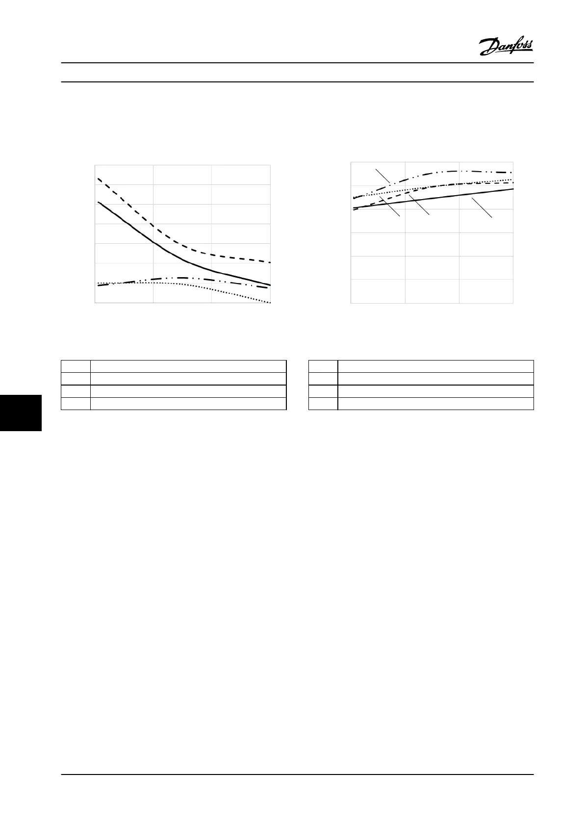
Motor cable length, m (ft)
dU/dt (kV/µs)
0
100
(328)
200
(656)
0.50
1.00
1.50
2.00
2.50
3.00
3.50
1
2
3
4
300
(984)
e30bu004.10
1 Unshielded cable with no lter
2 Shielded cable with no lter
3 Unshielded cable with dU/dt lter
4 Shielded cable with dU/dt lter
Figure 10.17 dU/dt at Motor Terminals for Enclosures E1h/E3h,
380–480 V
Motor cable length, m (ft)
Vpp/Vline
0
100
(328)
200
(656)
0.50
1.00
1.50
2.00
2.50
3.00
300
(984)
e30bu005.10
1
2 3
4
1 Unshielded cable with dU/dt lter
2 Shielded cable with dU/dt lter
3 Shielded cable with no lter
4 Unshielded cable with no lter
Figure 10.18 Peak Voltages at Motor Terminals for Enclosures
E1h/E3h, 380–480 V
Electrical Installation Con...
VLT
®
AQUA Drive FC 202
176 Danfoss A/S © 01/2018 All rights reserved. MG22B222
1010

 Loading...


