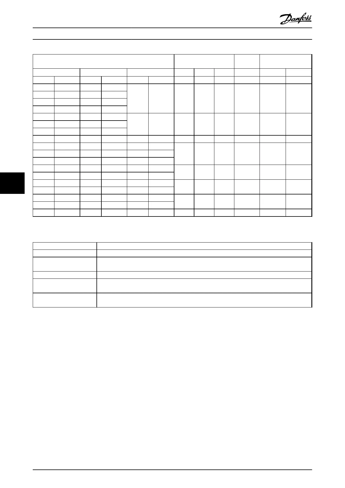
Frequency converter power and current ratings Filter current rating
Switching
frequency
Ordering no.
525-600 V 690 V 525-550 V 50 Hz 60 Hz 100 Hz
IP00
IP20/23
1)
[kW] [A] [kW] [A] [kW] [A] [A] [A] [A] kHz
0.75 1.7 1.1 1.6
- - 4.5 4 3 4 130B7335 130B7356
1.1 2.4 1.5 2.2
1.5 2.7 2.2 3.2
2.2 3.9 3.0 4.5
3 4.9 4.0 5.5
- - 10 9 7 4 130B7289 130B73244 6.1 5.5 7.5
5.5 9 7.5 10
7.5 11 11 13 7.5 14 13 12 9 3 130B3195 130B3196
11 18 15 18 11 19
28 26 21 3 130B4112 130B4113
15 22 18.5 22 15 23
18.5 27 22 27 18 28
22 34 30 34 22 36
45 42 33 3 130B4114 130B4115
30 41 37 41 30 48
37 52 45 52 37 54
76 72 57 3 130B4116 130B4117*
45 62 55 62 45 65
55 83 75 83 55 87
115 109 86 3 130B4118 130B4119*
75 100 90 100 75 105
90 131 - - 90 137 165 156 124 2 130B4121 130B4124*
Table 7.27 Sine-Wave Filters for Frequency Converters with 525-690 V
1) Ordering numbers marked with * are IP23.
Parameter
Setting
14-00 Switching Pattern [1] SFAVM
14-01 Switching Frequency Set according the individual filter. Listed at filter product label and in output filter manual. Sine-wave
filters are not allowing lower switching frequency than specified by the individual filter.
14-55 Output Filter [2] Sine-Wave Filter Fixed
14-56 Capacitance Output
Filter
Set according to the individual filter. Listed at filter product label and in output filter manual (only
required for FLUX operation).
14-57 Inductance Output Filter Set according to the individual filter. Listed at filter product label and in output filter manual (only
required for FLUX operation).
Table 7.28 Parameter Settings for Sine-wave Filter Operation
How to Order
VLT
®
AutomationDrive FC 301/FC 302 Design Guide, 0.25-75 kW
104 MG33BF02 - Rev. 2013-12-20
77

 Loading...


