All bits in the STW are set to ’0’ if the connection between
the Interbus option and the frequency converter is lost, or
an internal communication problem has occurred.
12.13.3 Bus Speed Reference Value
Speed reference value is transmitted to the frequency
converter in a relative value in %. The value is transmitted
in the form of a 16-bit word; in integers (0-32767) the
value 16384 (4000 hex) corresponds to 100%. Negative
figures are formatted by means of 2’s complement. The
actual output frequency (MAV) is scaled in the same way
as the bus reference.
Actual output
freq.
STW
Follower-master
Speed ref.CTW
Master-follower
16bit
130BA276.11
Illustration 12.18 Actual Output Frequency (MAV)
The reference and MAV are scaled as follows:
Reverse Forward
Par.3-00 set to
(1) -max- +max
Max reference Max reference
Par.3-00 set to
(0) min-max
Max reference
Forward
Min reference
100%
(4000hex)
-100%
(C000hex)
0%
(0hex)
Par.3-03 0 Par.3-03
Par.3-03
(4000hex)(0hex)
0% 100%
Par.3-02
130BA277.10
Illustration 12.19 Reference and MAV
12.13.4
Control Word according to
PROFIdrive Profile (CTW)
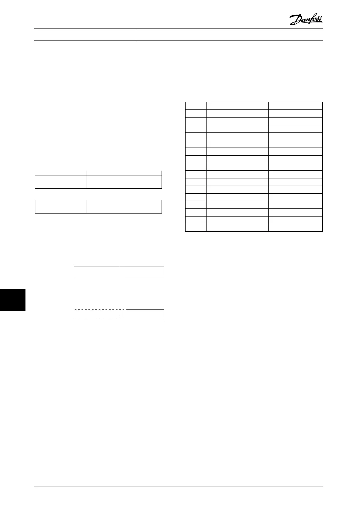
The control word is used to send commands from a master
(for example, a PC) to a follower.
Bit Bit=0 Bit=1
00 OFF 1 ON 1
01 OFF 2 ON 2
02 OFF 3 ON 3
03 Coasting No coasting
04 Quick stop Ramp
05 Hold frequency output Use ramp
06 Ramp stop Start
07 No function Reset
08 Jog 1 OFF Jog 1 ON
09 Jog 2 OFF Jog 2 ON
10 Data invalid Data valid
11 No function Slow down
12 No function Catch up
13 Parameter set-up Selection lsb
14 Parameter set-up Selection msb
15 No function Reverse
Table 12.24 Control Word Bits
Explanation of the control bits
Bit 00, OFF 1/ON 1
Normal ramp stops using the ramp times of the actual
selected ramp.
Bit 00="0" leads to the stop and activation of the output
relay 1 or 2 if the output frequency is 0 Hz and if [Relay
123] has been selected in 5-40 Function Relay.
When bit 0="1", the frequency converter is in State 1:
“Switching on inhibited”.
Bit 01, OFF 2/ON 2
Coasting stop
When bit 01="0", a coasting stop and activation of the
output relay 1 or 2 occurs if the output frequency is 0 Hz
and if [Relay 123] has been selected in 5-40 Function Relay.
Bit 02, OFF 3/ON 3
Quick stop using the ramp time of 3-81 Quick Stop Ramp
Time. When bit 02="0", a quick stop and activation of the
output relay 1 or 2 occurs if the output frequency is 0 Hz
and if [Relay 123] has been selected in 5-40 Function Relay.
When bit 02="1", the frequency converter is in State 1:
“Switching on inhibited”.
Bit 03, Coasting/No coasting
Coasting stop Bit 03="0" leads to a stop.
When bit 03="1", the frequency converter can start if the
other start conditions are satisfied.
RS-485 Installation and Set...
VLT
®
AutomationDrive FC 301/FC 302 Design Guide, 0.25-75 kW
190 MG33BF02 - Rev. 2013-12-20
1212

 Loading...


