Testing conditions
EN 60 947-8
Measurement voltage surge resistance 6000 V
Overvoltage category III
Pollution degree 2
Measurement isolation voltage Vbis 690 V
Reliable galvanic isolation until Vi 500 V
Perm. ambient temperature -20 °C to +60 °C
EN 60068-2-1 Dry heat
Moisture 5-95%, no condensation permissible
Vibration resistance 10 to 1000 Hz 1.14 g
Shock resistance 50 g
Safety system values
EN 61508 for Tu = 75 °C ongoing
SIL 2 for maintenance cycle of 2 years
1 for maintenance cycle of 3 years
HFT 0
PFD (for yearly functional test) 4.10 *10
-3
SFF 78%
λ
s
+ λ
DD
8494 FIT
λ
DU
934 FIT
Ordering number 130B1137
11.2.7
VLT
®
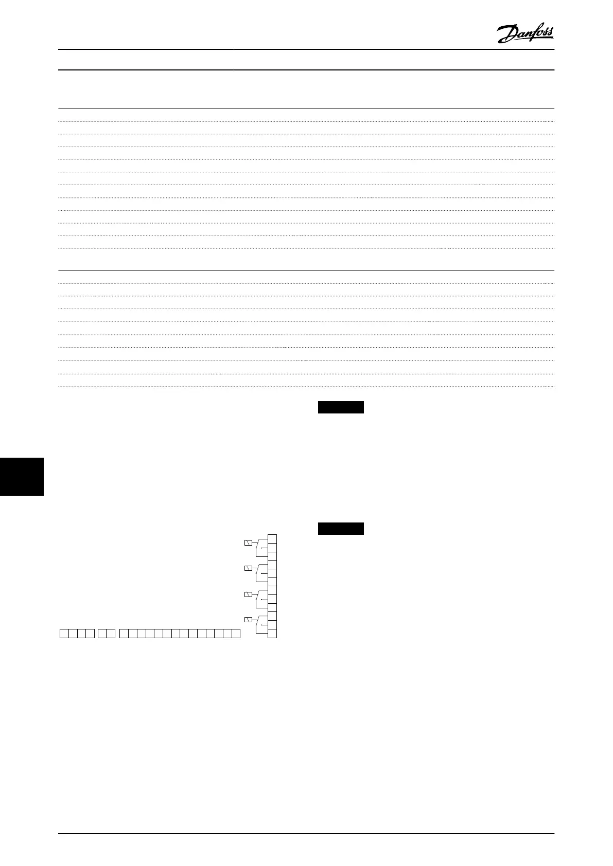
Extended Relay Card MCB 113
The MCB 113 adds 7 digital inputs, 2 analog outputs and 4
SPDT relays to the standard I/O of the frequency converter
for increased flexibility and to comply with the German
NAMUR NE37 recommendations.
The MCB 113 is a standard C1 option for the VLT
®
AutomationDrive and is automatically detected after
mounting.
130BA965.10
121110987654321
4321 12111098765432121 13 14
+
-
+
-
+
-
+
-
+
-
+
-
+
-
+
-
+
-
+
-
A03
A03
Ext. 24 VDC
DI1
DI2
DI3
DI4
DI5
DI6
DI7
X45/ X48/ X46/
X47/
Relay 3 Relay 4 Relay 5 Relay 6
Illustration 11.17 Electrical Connections of MCB 113
MCB 113 can be connected to an external 24 V on X58/ to
ensure galvanical isolation between the VLT
®
AutomationDrive and the option card. If galvanical
isolation is not needed, the option card can be supplied
through internal 24 V from the frequency converter.
NOTICE
It is OK to combine 24 V signals with high voltage
signals in the relays as long as there is one unused relay
in-between.
To setup MCB 113, use parameter groups 5-1* Digital input,
6-7* Analog Output 3, 6-8* Analog output 4, 14-8* Options,
5-4* Relays and 16-6* Inputs and Outputs.
NOTICE
In parameter group 5-4* Relay, Array [2] is relay 3, array
[3] is relay 4, array [4] is relay 5 and array [5] is relay 6
Options and Accessories
VLT
®
AutomationDrive FC 301/FC 302 Design Guide, 0.25-75 kW
162 MG33BF02 - Rev. 2013-12-20
1111

 Loading...


