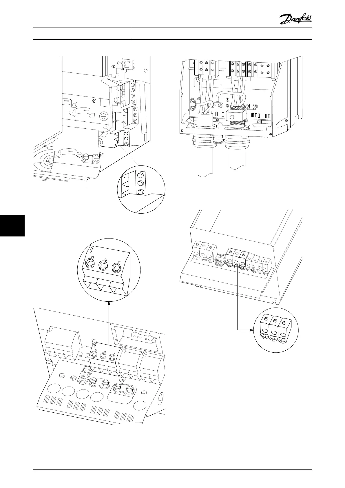
Illustration 9.33 Motor Connection for Enclosure B3
U
96
V
97
W
98
U
96
V
97
W
98
L1
91
L2
92
L3
93
DC-
88
DC+
89
R-
81
R+
82
130BA721.10
99
Illustration 9.34 Motor Connection for Enclosure B4
91
L1
92
L2
93
L3
96
U
97
V
98
W
88
DC-
89
DC+
81
R-
8
R+
130BA390.11
99
95
Illustration 9.35 Motor Connection Enclosures C1 and C2 (IP21/
NEMA Type 1 and IP55/66/NEMA Type 12)
130BA740.10
DC-
DC+
R-
R+
88
89
81
82
97
U
V
W
99
96
98
L1
91
L2
92
L3
93
97
U
V
W
96
98
Illustration 9.36 Motor Connection for Enclosures C3 and C4
9.5 Earth Leakage Current Protection
Follow national and local codes regarding protective
earthing of equipment with a leakage current > 3,5 mA.
The protective earth connection must have a cross section
of minimum 10 mm
2
or consist of 2 separate wires each
with the same cross section as the phase wires. Frequency
converter technology implies high frequency switching at
high power. This generates a leakage current in the earth
connection.
Electrical Installation
VLT
®
AutomationDrive FC 301/FC 302 Design Guide, 0.25-75 kW
134 MG33BF02 - Rev. 2013-12-20
99

 Loading...


