4.2.14 Smart Logic Control (SLC)
Smart Logic Control (SLC) is a sequence of user-defined
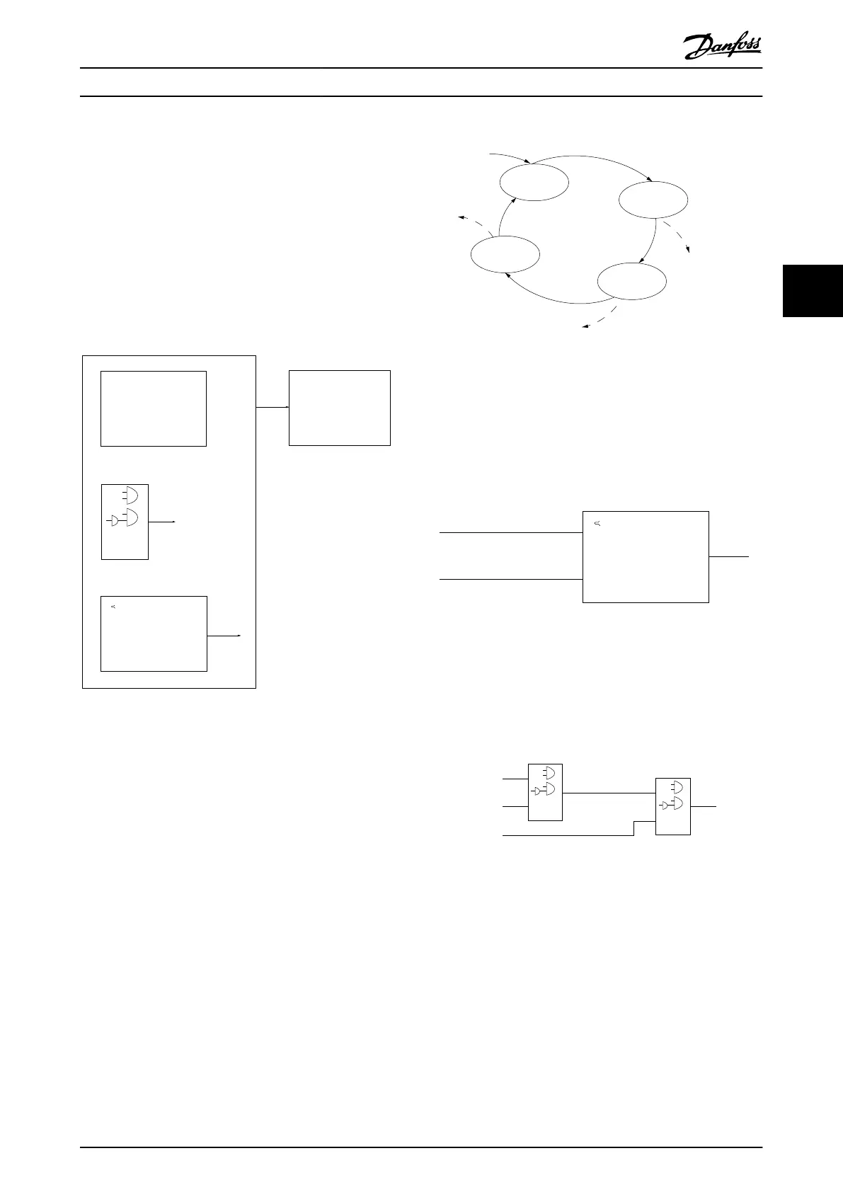
actions (see 13-52 SL Controller Action [x]) executed by the
SLC when the associated user defined event (see 13-51 SL
Controller Event [x]) is evaluated as TRUE by the SLC.
The condition for an event can be a particular status or
that the output from a Logic Rule or a Comparator
Operand becomes TRUE. That leads to an associated
Action as shown in Illustration 4.4.
. . .
. . .
Par. 13-11
Comparator Operator
Par. 13-43
Logic Rule Operator 2
Par. 13-51
SL Controller Event
Par. 13-52
SL Controller Action
130BB671.13
Coast
Start timer
Set Do X low
Select set-up 2
. . .
Running
Warning
Torque limit
Digital input X 30/2
. . .
=
TRUE longer than..
. . .
. . .
Illustration 4.4 SCL Event and Action
Events and actions are each numbered and linked in pairs
(states). This means that when event [0] is fulfilled (attains
the value TRUE), action [0] is executed. After this, the
conditions of event [1] is evaluated and if evaluated TRUE,
action [1] is executed and so on. Only one event is
evaluated at any time. If an event is evaluated as FALSE,
nothing happens (in the SLC) during the current scan
interval and no other events are evaluated. This means that
when the SLC starts, it evaluates event [0] (and only event
[0]) each scan interval. Only when event [0] is evaluated
TRUE, the SLC executes action [0] and starts evaluating
event [1]. It is possible to programme from 1 to 20 events
and actions.
When the last event/action has been executed, the
sequence starts over again from event [0]/action [0].
Illustration 4.5 shows an example with 4 event/actions:
130BA062.14
State 1
13-51.0
13-52.0
State 2
13-51.1
13-52.1
Start
event P13-01
State 3
13-51.2
13-52.2
State 4
13-51.3
13-52.3
Stop
event P13-02
Stop
event P13-02
Stop
event P13-02
Illustration 4.5 Order of Execution when 4 Events/Actions are
Programmed
Comparators
Comparators are used for comparing continuous variables
(i.e. output frequency, output current, analog input etc.) to
fixed preset values.
Par. 13-11
Comparator Operator
=
TRUE longer than.
. . .
. . .
Par. 13-10
Comparator Operand
Par. 13-12
Comparator Value
130BB672.10
Illustration 4.6 Comparators
Logic Rules
Combine up to 3 boolean inputs (TRUE/FALSE inputs) from
timers, comparators, digital inputs, status bits and events
using the logical operators AND, OR, and NOT.
. . .
. . .
. . .
. . .
Par. 13-43
Logic Rule Operator 2
Par. 13-41
Logic Rule Operator 1
Par. 13-40
Logic Rule Boolean 1
Par. 13-42
Logic Rule Boolean 2
Par. 13-44
Logic Rule Boolean 3
130BB673.10
Illustration 4.7 Logic Rules
4.2.15 Safe Torque Off
For information about Safe Torque Off, refer to the VLT
®
FC
Series Safe Torque Off Operating Instructions.
Product Features
VLT
®
AutomationDrive FC 301/FC 302 Design Guide, 0.25-75 kW
MG33BF02 - Rev. 2013-12-20 43
4 4

 Loading...


