NOTICE
Protection mode and trip delay features (14-25 Trip Delay
at Torque Limit and 14-26 Trip Delay at Inverter Fault)
may delay the activation of the mechanical brake in an
alarm condition. These features must be disabled in
hoisting applications.
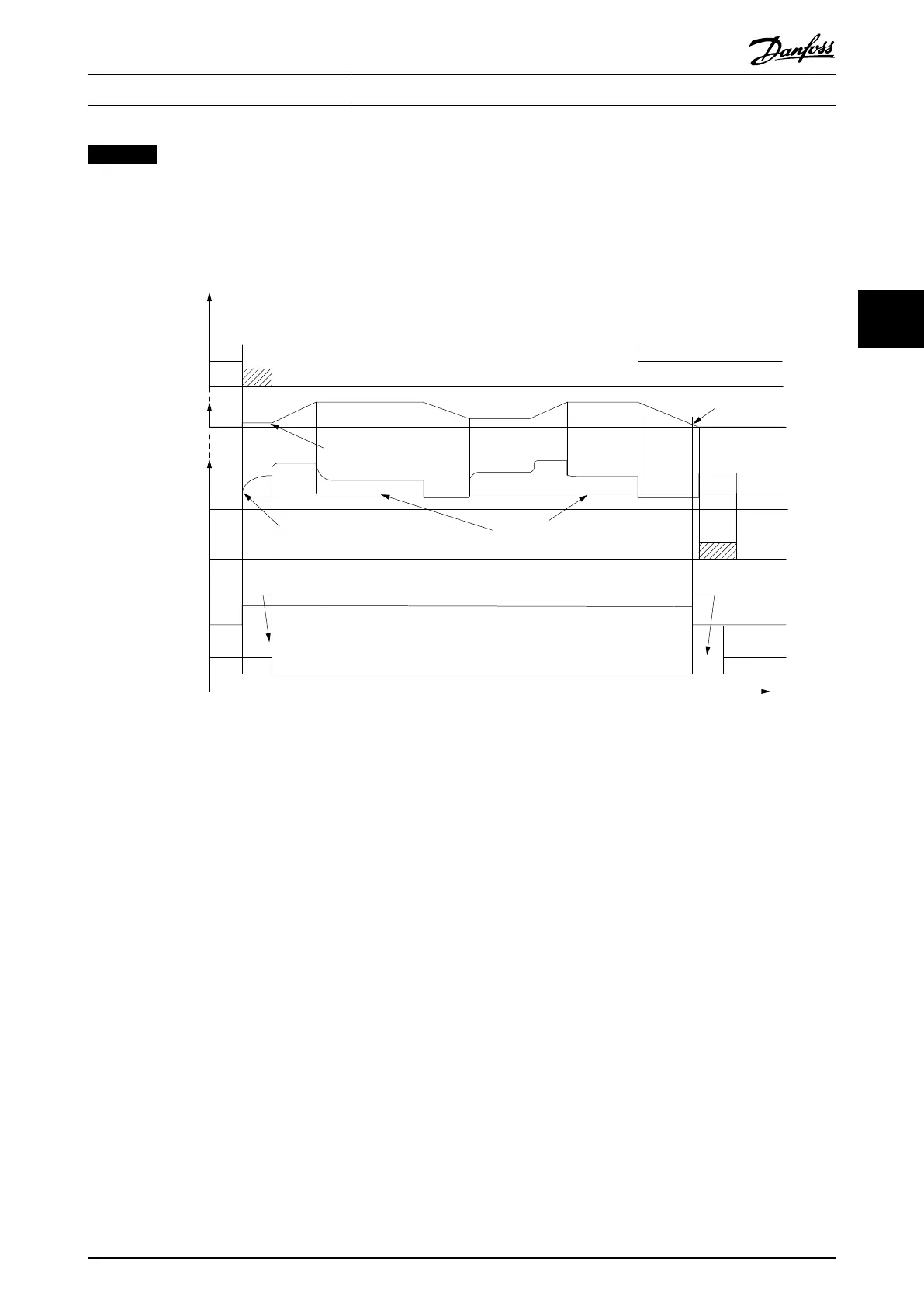
Start
term.18
1=on
0=o
Shaft speed
Start delay time
on
o
Brake delay time
Time
Output current
Relay 01
Pre-magnetizing
current or
DC hold current
Reaction time EMK brake
Par 2-20
Release brake current
Par 1-76 Start current/
Par 2-00 DC hold current
Par 1-74
Start speed
Par 2-21
Activate brake
speed
Mechanical brake
locked
Mechanical brake
free
Par 1-71
Par 2-23
130BA074.12
Illustration 4.2 Mechanical Brake
4.2.13
Closed Loop Mechancial Brake
Control/Hoist Mechanical Brake
The hoist mechanical break control supports the following
functions:
•
2 channels for mechanical brake feedback to offer
further protection against unintended behaviour
resulting from broken cable.
•
Monitoring of mechanical brake feedback
throughout the complete cycle. This helps protect
the mechanical brake - especially if more
frequency converters are connected to the same
shaft.
•
No ramp up until feedback confirms mechanical
brake is open.
•
Improved load control at stop. If 2-23 Activate
Brake Delay is set too short, W22 is activated and
the torque is not allowed to ramp down.
•
The transition when motor takes over the load
from the brake can be configured. 2-28 Gain
Boost Factor can be increased to minimise the
movement. For very smooth transition change
the setting from the speed control to the position
control during the change-over.
•
Set 2-28 Gain Boost Factor to 0 to enable
Position Control during 2-25 Brake
Release Time. This enables parameters
2-30 Position P Start Proportional Gain to
2-33 Speed PID Start Lowpass Filter Time
which are PID parameters for the
Position Control.
Product Features
VLT
®
AutomationDrive FC 301/FC 302 Design Guide, 0.25-75 kW
MG33BF02 - Rev. 2013-12-20 41
4 4

 Loading...


