10 Application Examples
10.1 Commonly Used Applications
The examples in this section are intended as a quick
reference for common applications.
•
Parameter settings are the regional default values
unless otherwise indicated (selected in
0-03 Regional Settings)
•
Parameters associated with the terminals and
their settings are shown next to the drawings
•
Where switch settings for analog terminals A53 or
A54 are required, these are also shown
CAUTION
Thermistors must use reinforced or double insulation to
meet PELV insulation requirements.
Parameters
FC
+24 V
+24 V
D IN
D IN
D IN
COM
D IN
D IN
D IN
D IN
+10 V
A IN
A IN
COM
A OUT
COM
12
13
18
19
20
27
29
32
33
37
50
53
54
55
42
39
130BB929.10
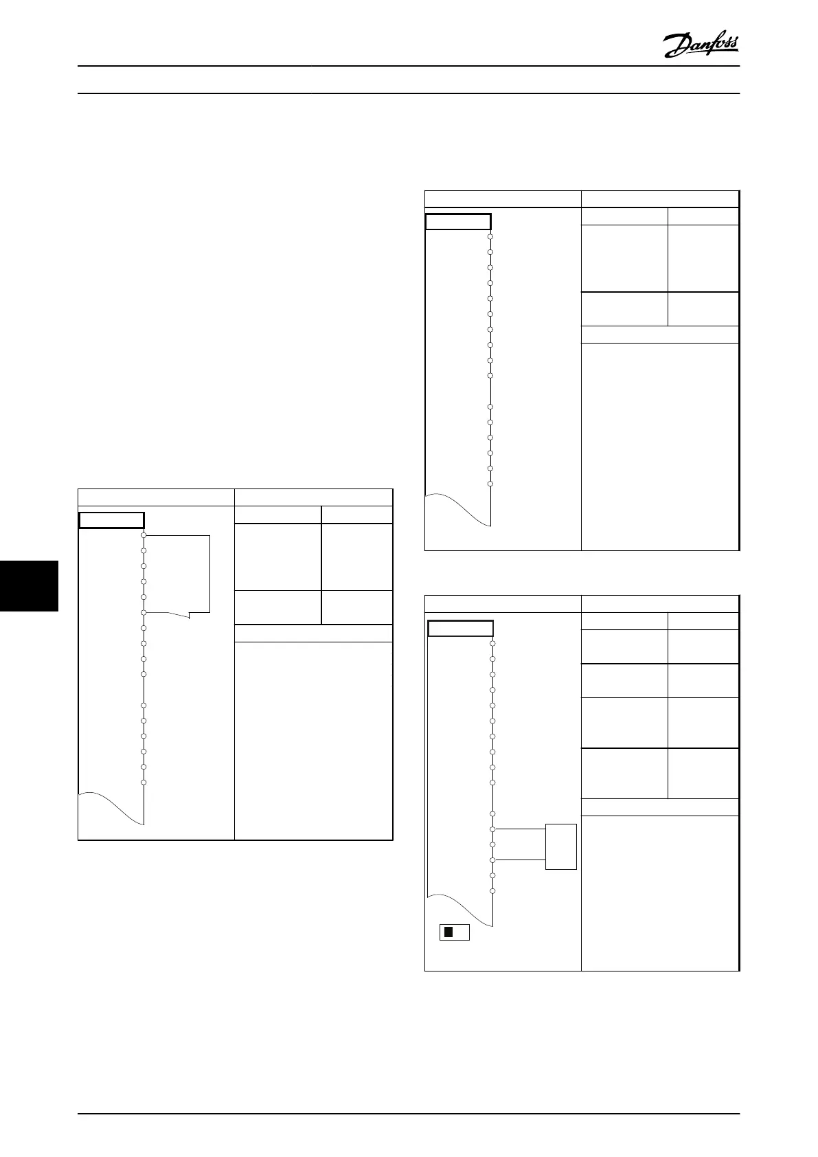
Function Setting
1-29 Automatic
Motor
Adaptation
(AMA)
[1] Enable
complete
AMA
5-12 Terminal 27
Digital Input
[2]* Coast
inverse
*=Default Value
Notes/comments: Parameter
group 1–2* Motor Data must be
set according to motor
Table 10.1 AMA with T27 Connected
Parameters
FC
+24 V
+24 V
D IN
D IN
D IN
COM
D IN
D IN
D IN
D IN
+10 V
A IN
A IN
COM
A OUT
COM
12
13
18
19
20
27
29
32
33
37
50
53
54
55
42
39
130BB930.10
Function Setting
1-29 Automatic
Motor
Adaptation
(AMA)
[1] Enable
complete
AMA
5-12 Terminal 27
Digital Input
[0] No
operation
*=Default Value
Notes/comments: Parameter
group 1–2* Motor Data must be
set according to motor
Table 10.2 AMA without T27 Connected
Parameters
FC
+24 V
+24 V
D IN
D IN
D IN
COM
D IN
D IN
D IN
D IN
+10
A IN
A IN
COM
A OUT
COM
12
13
18
19
20
27
29
32
33
37
50
53
54
55
42
39
A53
U - I
-10 - +10V
+
-
130BB926.10
Function Setting
6-10 Terminal 53
Low Voltage
0.07 V*
6-11 Terminal 53
High Voltage
10 V*
6-14 Terminal 53
Low Ref./Feedb.
Value
0 RPM
6-15 Terminal 53
High Ref./Feedb.
Value
1,500 RPM
*=Default Value
Notes/comments:
Table 10.3 Analog Speed Reference (Voltage)
Application Examples
VLT
®
AutomationDrive FC 301/FC 302 Design Guide, 0.25-75 kW
144 MG33BF02 - Rev. 2013-12-20
1010

 Loading...


