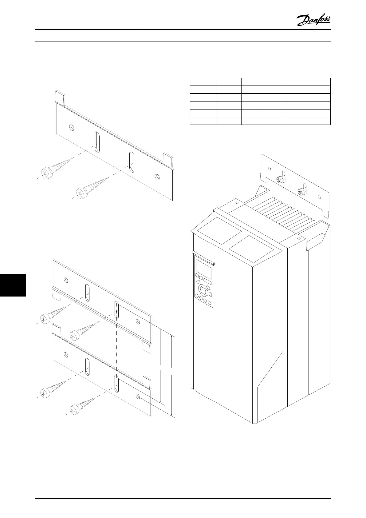
11.4.8 Mounting Bracket for Enclosure
Types A5, B1, B2, C1 and C2
Step 1
Illustration 11.30 Lower Bracket
Position the lower bracket and mount it with screws. Do
not tighten the screws completely since this will make it
difficult to mount the frequency converter.
Step 2
Illustration 11.31 Upper Bracket
Measure distance A or B, and position the upper bracket,
but do not tighten it. See dimensions in Table 11.16.
Enclosure IP A [mm] B [mm] Ordering number
A5 55/66 480 495 130B1080
B1 21/55/66 535 550 130B1081
B2 21/55/66 705 720 130B1082
B3 21/55/66 730 745 130B1083
B4 21/55/66 820 835 130B1084
Table 11.16 Details
Step 3
Illustration 11.32 Positioning
Options and Accessories
VLT
®
AutomationDrive FC 301/FC 302 Design Guide, 0.25-75 kW
174 MG33BF02 - Rev. 2013-12-20
1111

 Loading...


